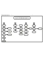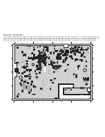
3 - 4
3 - 4
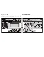
SERVICE POSITIONS
Service position A (Main Unit)
Note:In some service positions the components or copper patterns of one board may risk touching its neighbouring pc boards or
metallic parts. To prevent such short-circuit use a piece of hard paper or other insulating material between them.
Service position B (Subwoofer)
Summary of Contents for HTS6520/55
Page 7: ...1 7 ...
Page 8: ...1 8 ...
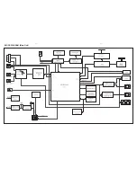
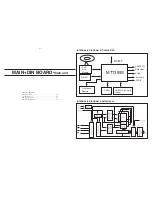
Page 17: ...4 1 4 1 BLOCK DIAGRAM Main Unit ...
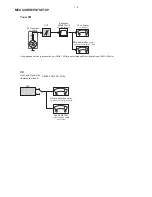
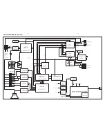
Page 19: ...4 3 4 3 BLOCK DIAGRAM Subwoofer TI5342LA TI5342LA TI5342LA TI5342LA TAS5508 ...
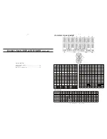
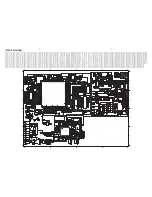
Page 35: ...9 1 9 1 IPOD BOARD main unit TABLE OF CONTENTS Circuit Diagram 9 2 PCB Layout View 9 3 ...
Page 51: ...13 1 REVISION LIST Version 1 0 Initial release ...


