1-6
Chapter 1: Overview
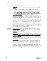
Standard AP Mounting Options
Optional hardware kits are available to mount the Standard ITS Smart-hopping APs
to a wall, above a ceiling tile, or below a ceiling tile.
ITS Core Access
Points
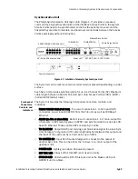
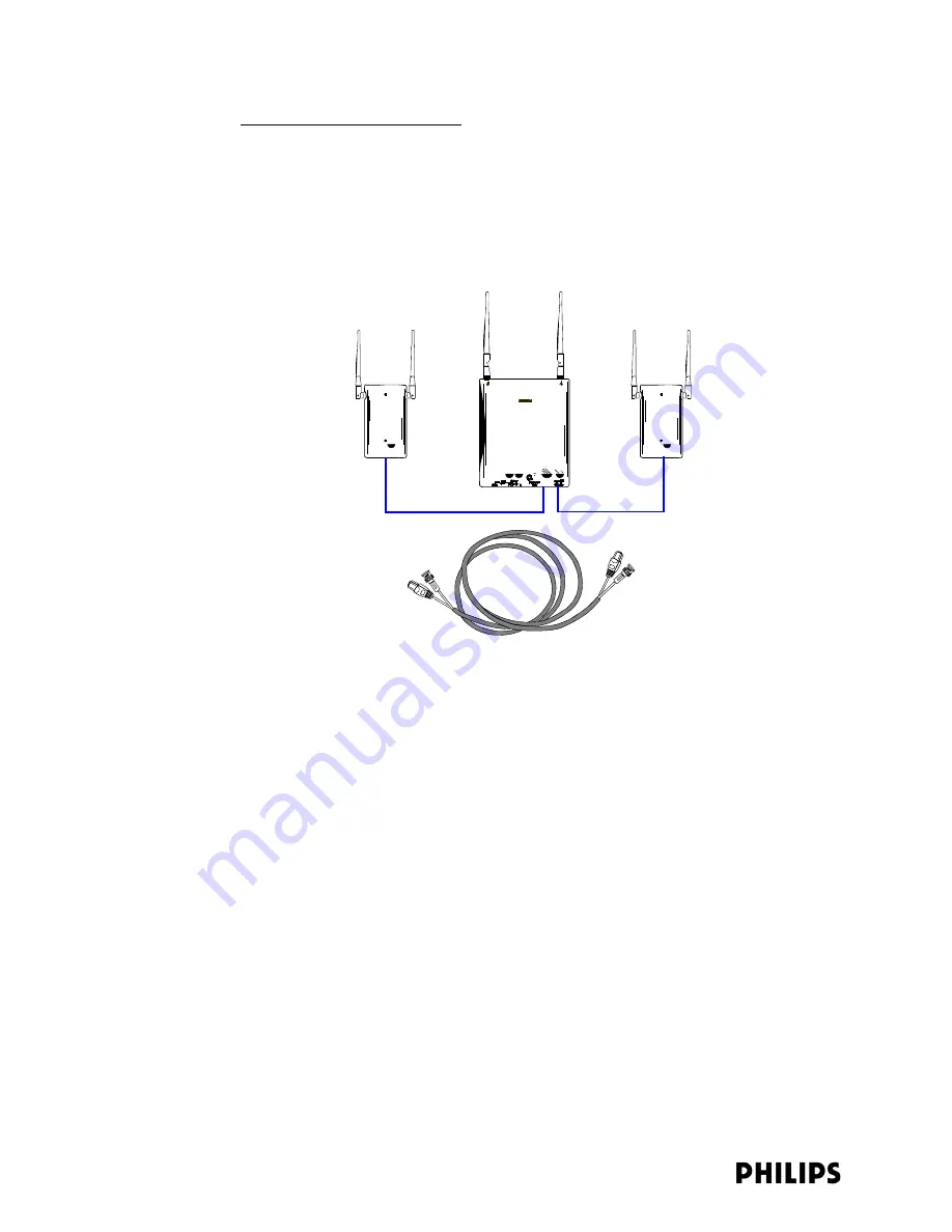
The IntelliVue Telemetry System Core Smart-hopping Access Point (AP), Model
ITS4843A, (Figure 1-2) provides an air-link to transmit and receive data between ITS
wireless clients and the Philips IntelliVue Information Center via the ITS
infrastructure.
The Core AP is a modular antenna infrastructure consisting of a Core AP (CAP) with
up to two connected Model ITS4846A Remote Antennas (RAs). A 68-foot (20.7m)
coaxial and unshielded twisted pair (UTP) cable bundle is used to connect a Remote
Antenna to a Core AP. Core APs are only available for the 1.4 GHz ITS.
The effective range of the Core AP and of each Remote Antenna is typically 32 feet.
The Core AP always supports a maximum of 18 wireless clients (i.e., patient-worn
transceivers or bedside monitors) regardless of its component configuration. A Core
AP alone supports 18 wireless clients. When used with a single RA, the Core AP
supports nine wireless clients and its connected RA supports nine wireless clients
(9+9=18). When used with two RAs, the Core AP supports six wireless clients and
its connected RAs each support six wireless clients (6+6+6=18).
When monitored patients are ambulatory, data roaming is handled seamlessly
between the other IntelliVue Access Points in the system. The Core AP and each RA
are always used with their two supplied antennas installed. The Core AP and its
attached Remote Antennas can be mounted out of the way on corridor walls, or
above or below ceiling tiles.
Philips provides ITS Core Access Points for the 1.4 GHz US Wireless Medical
Telemetry Service (WMTS) band (P/N 862228) with one or two optional Remote
Antennas.
Figure 1-4: IntelliVue Telemetry System Core Access Point (Model ITS4843A)
Core AP
Remote
Antenna
Remote
Antenna
68 ft. Coax and
UTP Cable Bundle
Summary of Contents for IntelliVue Telemetry System Infrastructure
Page 8: ...viii Contents ...
Page 14: ...xiv About This Guide ...
Page 100: ...3 22 Chapter 3 Installing and Configuring the ITS Figure 3 10 APC Filter Configuration Screen ...
Page 162: ...5 12 Chapter 5 Troubleshooting and Testing ...
Page 168: ...A 6 Chapter A Installing Multiple ITSs at a Single Hospital Site ...
Page 180: ...Index 8 Index ...


