IntelliVue Telemetry System Infrastructure Components
IntelliVue Telemetry System Infrastructure Installation and Service Guide
1
-
9
• Remote Antenna - The Core AP provides two LEDs on each RJ-45 UTP cable
connector that provides status on a connected Remote Antenna:
- RA Connection - Lights GREEN to indicate a RA is connected to the Core AP.
- RA Power - Lights YELLOW to indicate connected RA is receiving power from
the Core AP.
The Remote Antenna provides the following status LEDs.
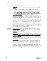
• Remote Antenna Status LEDs - The green and yellow LEDs above the
RJ-45 UTP cable connector to the Core AP provide status on the Remote
Antenna as summarized below.
Core AP Mounting Options
Wall-mounting hardware is standard. An optional above/below ceiling mount kit is
available.
Access Point Controller
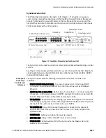
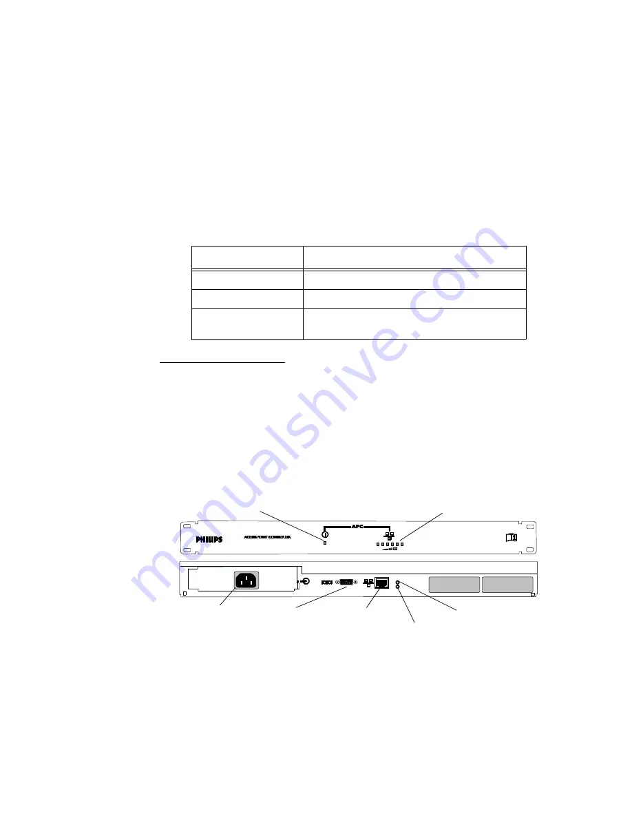
The multi-functional Philips Access Point Controller (APC) (Figure 1-6) controls the
data flow of patient-worn transceivers as the patients move about the coverage
area between the IntelliVue Access Points. It also can be used to configure
parameters of the APs—all via its Graphical User Interface (GUI).
The APC provides System Alerts such as loss of synchronization, high data loss, AP
hardware failure, and over capacity. Additionally, when redundant APCs are
installed, the APC will provide a System Alert for APC hardware or software failure. It
can be rack mounted (recommended) or placed freestanding on a flat surface.
Table 1-3: Remote Antenna Status LEDs
Green/Yellow LEDs
Remote Antenna Status
Off/Off
No connection to or power from Core AP.
Flash Green/Yellow
Remote Antenna is running self-test/Power on.
Solid Green/Yellow
Connection to Core AP is Successful/Power On.
This is the expected normal operational status.
Figure 1-6: IntelliVue Telemetry System Access Point Controller
Power LED
Network Utilization LEDs
100-240V~
50/60 Hz,1.5A
100 Base-T
Link/ACT
Power Receptacle
Serial Port
Ethernet Port
100 Base-T LED
Link/ACT LED
Summary of Contents for IntelliVue Telemetry System Infrastructure
Page 8: ...viii Contents ...
Page 14: ...xiv About This Guide ...
Page 100: ...3 22 Chapter 3 Installing and Configuring the ITS Figure 3 10 APC Filter Configuration Screen ...
Page 162: ...5 12 Chapter 5 Troubleshooting and Testing ...
Page 168: ...A 6 Chapter A Installing Multiple ITSs at a Single Hospital Site ...
Page 180: ...Index 8 Index ...


