IntelliVue Telemetry System Infrastructure Components
IntelliVue Telemetry System Infrastructure Installation and Service Guide
1
-
11
Synchronization Unit
The Philips Synchronization Unit (Sync Unit) (Figure 1-7) provides a necessary
common clock signal to synchronize all the IntelliVue Access Points in the system.
Access Points need to be synchronized so that as the patients move around the
hospital they are able to maintain and hand over connections between the Access
Points seamlessly without interruption.
The Sync Unit can be rack mounted (recommended) or placed freestanding on a flat
surface.
Each Sync Unit provides synchronization for up to 12 Access Points (AP). Maximum
cable length between a Switch/PoE Unit/Sync Unit/Access Point is 100m (328ft.)
(normal LAN Ethernet rules).
Front-panel
Connectors,
Controls, and
Indicators
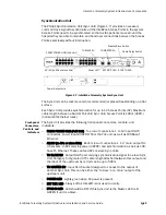
The Sync Unit provides the following front-panel connectors, controls, and
indicators:
• FROM POWER HUB (PoE Unit) - Top row of connectors. 1 to 12 input RJ-45
connectors, power inputs (48VDC) from the PoE unit, as well as 100Base-T
Ethernet.
• AP/SU (to APs or slave SUs) - Bottom row of connectors. 1 -12 ‘main’ output RJ-
45 sockets, to APs carrying power (48VDC) and synchronization as well as 100-
base-TX Ethernet. These can feed APs or slave Sync Units.
• TO SLAVE SU - Output RJ-45 port carrying synchronization signal to a slave Sync
Unit. Category 5 (or greater) UTP cable length attached between this output and
the input of the upstream Sync Unit can be up to 500m.
• TO MASTER SU - Input RJ-45 socket designed to connect to the output of
another Sync Unit. This can be either the ‘to slave’ or a ‘main’ output of the
upstream unit
• POWER LED - Lights green when AC power is present.
• EXT REF. LED - Always off as this LED is not used currently.
• SYNC IN LED - LED should be OFF if this Sync Unit is the Master. LED is lit
GREEN if unit is a Slave.
Figure 1-7: IntelliVue Telemetry System Sync Unit
Power Receptacle
1 2 3 4 5 6 7 8 9 10 11 12
SLAVE SU
TO
POWER EXT REF SYNC. IN
MASTER
CABLE DELAY
EXT. 10MHz REF.
SLAVE
1
2
3
10
4
5
6
8
7
9
1 2 3 4 5 6 7 8 9 10 11 12
MASTER SU
TO
FROM
POWER
HUB
AP/SU
FROM POWER HUB (PoE Unit)
AP/SU (to APs or slave SUs)
TO SLAVE SU
TO MASTER SU
Power LED
EXT REF. LED SYNC IN LED
Master/Slave Switch
Cable Delay Switch
Summary of Contents for IntelliVue Telemetry System Infrastructure
Page 8: ...viii Contents ...
Page 14: ...xiv About This Guide ...
Page 100: ...3 22 Chapter 3 Installing and Configuring the ITS Figure 3 10 APC Filter Configuration Screen ...
Page 162: ...5 12 Chapter 5 Troubleshooting and Testing ...
Page 168: ...A 6 Chapter A Installing Multiple ITSs at a Single Hospital Site ...
Page 180: ...Index 8 Index ...


