1-12
Chapter 1: Overview
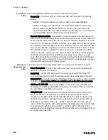
• MASTER/SLAVE Toggle Switch - MASTER/SLAVE toggle switch (set manually) to
indicate the master SU of an installation. This MASTER switch disables the
alarm that would be generated by the lack of an upstream unit to provide a
reference signal to this unit. Slave units should receive a reference feed from a
master SU, and should be switched to the SLAVE position (operation). If the
reference feed fails, these units will free-run, and will also generate a technical
alarm.
• CABLE DELAY Switch - 10 Position rotary step switch compensates for cable
delay - lowest delay position 1 to highest delay position 10. Each switch
increment represents 50 m cable length.
• EXT 10MHz REF - Not used currently.
Rear-panel
Connectors
The Sync Unit has a single rear-panel connector, its AC power cord receptacle.
Connect the Sync Unit to an AC power source that provides 100 - 240 VAC, 1.5A
max, at 50/60Hz (autoranging).
Power over Ethernet Unit
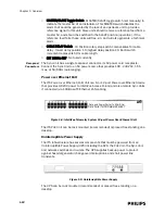
The ITS Power over Ethernet (PoE) Unit is a 6- or 12-port Power-over-Ethernet device
that provides 48 VDC power to IntelliVue Access Points (and also remote Sync Units
if connected) via 100-Base-TX Ethernet LAN cabling.
The ITS PoE Unit can be rack mounted (recommended) or placed free standing on a
desktop.
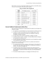
Uninterruptible Power Supply
The ITS infrastructure has several components that must be powered from an
Uninterruptible Power Supply (UPS) including the APC, the PoE Unit, the Sync Unit,
and network switches and routers. The UPS supplies backup power to protect
against hospital generator changeover interruptions, and short power line
transients.
The UPS can be rack mounted (recommended) or placed free standing on a
desktop.
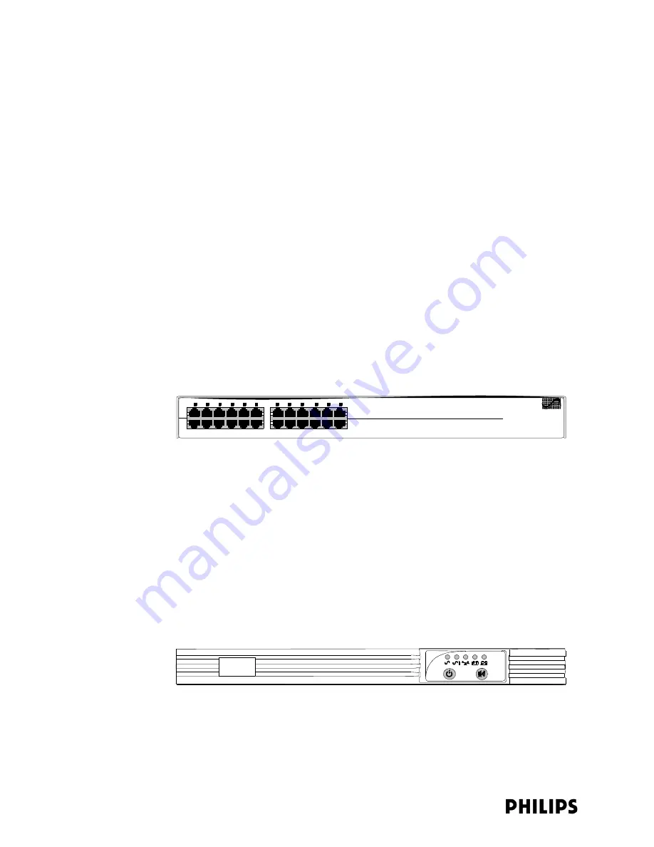
Figure 1-8: IntelliVue Telemetry System 12-port Power Over Ethernet Unit
Figure 1-9: Uninterruptible Power Supply
Data and Power Ports (To APs/SUs)
Data Ports (To ICN Network Switch)
Summary of Contents for IntelliVue Telemetry System Infrastructure
Page 8: ...viii Contents ...
Page 14: ...xiv About This Guide ...
Page 100: ...3 22 Chapter 3 Installing and Configuring the ITS Figure 3 10 APC Filter Configuration Screen ...
Page 162: ...5 12 Chapter 5 Troubleshooting and Testing ...
Page 168: ...A 6 Chapter A Installing Multiple ITSs at a Single Hospital Site ...
Page 180: ...Index 8 Index ...


