2-4
Chapter 2: Planning Your ITS Deployment
Performing a Physical Space Assessment
Assessing the physical space at the ITS deployment site requires that you:
• understand the radius of coverage provided by 1.4 GHz and 2.4 GHz Access
Points
• determine the number of ITS patient-worn transceivers and wireless bedside
monitors to be deployed
• determine optimal AP installation locations
• determine the number of APCs required to support the APs to be deployed
• locate IT equipment closets
• plan cable runs between ITS devices
• determine the number of UPSs required to support the ITS deployment
Understanding the Radius of Coverage (RoC) Metric
The radius of coverage (RoC) is the area for which a given access point can provide
RF coverage. Graphically, this is represented as a circle with the AP at its center. In
reality, the actual area of acceptable coverage has been demonstrated to be an
irregular shape, formed in large part by site structure such as walls, elevator shafts
and other materials that affect RF coverage. However as a starting point, a simple
circle can often be effectively used to represent coverage for a given AP.
The ITS design goal is to blanket the desired coverage area such that wireless
patient devices might move and be used throughout this area without losing
network connectivity. The actual usable radius of coverage value depends on the
building layout and construction techniques.
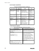
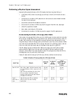
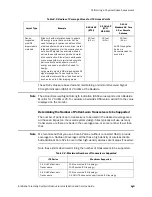
Table 2-1 lists the RoC values for ITS Access Points and Remote Antennas.
Table 2-1: Radius of Coverage Values for ITS Access Points
Layout Type
Example
2.4 GHz AP
(ETSI)
2.4 GHz AP
(FCC/
RSS-210)
1.4 GHz
Standard AP, Core
AP, or Remote
Antenna
Open air/LOS
Open “line of sight” (LOS) environment such
as a long hallway corridor or open ward with
no walls.
Note that when installing Core APs, a Core
AP alone (without connected Remote
Antennas) will generally provide sufficient
coverage for a LOS area.
60 feet
(18.3 m)
90 feet
(27.4 m)
60 feet
(18.3 m)
Typical
Patient Room
Area
Hospital wing area with concentrated
patient rooms and newer building
construction.
32 feet
(9.8 m)
50 feet
(15.2 m)
32 feet
(9.8 m)
Summary of Contents for IntelliVue Telemetry System Infrastructure
Page 8: ...viii Contents ...
Page 14: ...xiv About This Guide ...
Page 100: ...3 22 Chapter 3 Installing and Configuring the ITS Figure 3 10 APC Filter Configuration Screen ...
Page 162: ...5 12 Chapter 5 Troubleshooting and Testing ...
Page 168: ...A 6 Chapter A Installing Multiple ITSs at a Single Hospital Site ...
Page 180: ...Index 8 Index ...

