2-6
Chapter 2: Planning Your ITS Deployment
Determining AP Installation Locations
The ITS design goal is to blanket the coverage area with overlapping coverage cells
such that wireless patient devices might move and be used throughout this area
without losing network connectivity.
When determining where the APs should be installed, preference should be given to
the areas where patients spend the majority of their time.
In the ideal system, the number of walls that the RF signal must penetrate should
be minimized. Since wall penetration is a requirement in most all covered areas, the
AP should be placed on the side of the wall where the patient (and patient-worn
transceiver) spends the majority of the time. At the same time, the AP installation
location should maximize the amount of covered area. These objectives are
sometimes diametrically opposed. A rule of thumb to designing an optimal system
is to limit the wall penetrations for any given AP-to-transceiver connection to one.
The following sections describe the best employment of this approach for two
common types of patient room layouts.
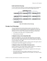
Symmetrical
Patient Room
Layout
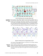
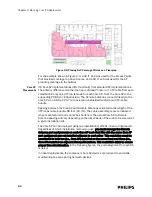
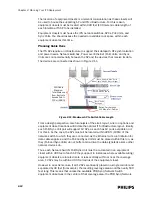
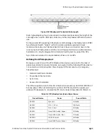
In Figure 2-2, patient rooms lie on either side of the hallway. With traditional corridor
widths of approximately 10 to 12 feet (3 to 3.6 m), and patient room depths of 12 to
18 feet (3.6 to 5.5 m), covering a wing side-to-side with APs placed along the
hallway centerline appears feasible (for a 32-foot (9.8 m) RoC). In many cases, this
method has been employed successfully, but in others not. Sites with dense wall
construction (typically older hospitals, high rise hospitals and/or hospitals built to
earthquake codes) often do not perform well using this method, especially if there
are bathrooms located in the outside edges of the patient rooms. As RF penetration
decreases at these types of sites, the typical method to achieve coverage is to
reduce the AP spacing in the hallway and add more APs. This sometimes works, but
is really concentrating APs in an area where the patient will not spend much time
(the hallway).
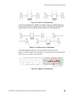
The analysis of coverage for hallway-placed APs is quantized quite simply to how
many pairs of rooms one AP can cover. Two to three pairs (4 to 6 rooms) is typical. In
cases where only one pair can be covered, you may want to consider placing APs in
every other room alternating side-to-side along the corridor.
ITS Wireless Clients
(Patient-worn transceivers
or bedside monitors)
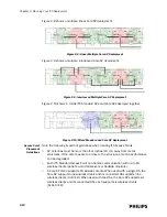
Each Standard 1.4/2.4 GHz AP supports up to 18 wireless clients.
A Core AP alone supports 18 wireless clients. When used with a
single RA, the Core AP supports nine wireless clients and its
connected RA supports nine wireless clients (9+9=18). When used
with two RAs, the Core AP supports six wireless clients and its
connected RAs each support six wireless clients (6+6+6=18).
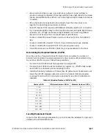
Table 2-2: Maximum Numbers of Transceivers Supported
ITS Device
Maximum Supported
Summary of Contents for IntelliVue Telemetry System Infrastructure
Page 8: ...viii Contents ...
Page 14: ...xiv About This Guide ...
Page 100: ...3 22 Chapter 3 Installing and Configuring the ITS Figure 3 10 APC Filter Configuration Screen ...
Page 162: ...5 12 Chapter 5 Troubleshooting and Testing ...
Page 168: ...A 6 Chapter A Installing Multiple ITSs at a Single Hospital Site ...
Page 180: ...Index 8 Index ...

