2-16
Chapter 2: Planning Your ITS Deployment
If the delay setting is not set correctly, the APs will not be synchronized properly
resulting in an intermittent loss of connectivity.
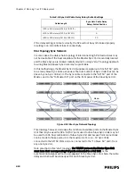
Star Topology Sync Network
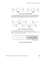
In some cases, the daisy-chain topology of interconnecting AP infrastructures may
not be desirable. If the best candidate for the Master Sync Unit is centrally located
and the Slave Syncs are located radially around it, using a “star” topology approach
to wiring Master/Slaves Sync Units may be preferable.
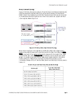
In this methodology, the Master Sync Unit supplies its signal out of its “AP/SU” ports
to as many Slave Sync Units as needed. The total number of Sync Units that can be
driven by one Sync Unit is 13. The Sync cable connects to the “AP/SU” port of the
Master, and to the “To Master SU” port on the front panel of the Slave Sync Unit.
This topology, however, decreases the number of available ports on the Master Sync
Unit that may be used for APs. ‘AP/SU’ ports used to drive Slave Sync Units may not
be used for APs. Any combination of Slave Sync Unit and Access Point connections
can be made to these ports, up to the maximum of 13 (i.e., 12 Sync Units
connected to the AP/SU Ports and one connected to the “To Slave SU” port), from
any one Sync Unit.
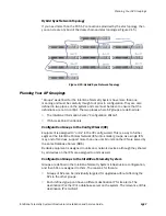
Note also that in this “star” topology, the 'AP/SU' ports on the Master Sync Unit
must have their corresponding PoE ports connected to a PoE Unit, or the
synchronization signal will not be propagated to the Slave Sync Unit. Also, the cable
delay switch should be properly set for each Slave Sync Unit.
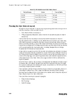
>350 to 400 meters (1148 to 1312 ft.)
8
>400 to 450 meters (1312 to 1476 ft.)
9
>450 to 500 meters (1476 to 1640 ft.)
10
Figure 2-14: Star Sync Network Topology
Table 2-5: Sync Unit Cable Delay Rotary Switch Settings
Cable Length
Sync Unit - Cable Delay
Rotary Switch Position
Master
Sync Unit
Summary of Contents for IntelliVue Telemetry System Infrastructure
Page 8: ...viii Contents ...
Page 14: ...xiv About This Guide ...
Page 100: ...3 22 Chapter 3 Installing and Configuring the ITS Figure 3 10 APC Filter Configuration Screen ...
Page 162: ...5 12 Chapter 5 Troubleshooting and Testing ...
Page 168: ...A 6 Chapter A Installing Multiple ITSs at a Single Hospital Site ...
Page 180: ...Index 8 Index ...

