Directions for Use
GB 5
L01.1A
3.
3. Directions for Use
6
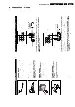
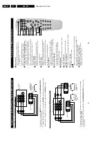
You can vie
w the playbac
k of
VCR tapes (Video Disc play
er
s,
camcor
der
s,
etc
.) b
y using the
A
UDIO
and
VIDEO INPUT soc
kets on the r
ear of the
TV
.
–
Connect the
VIDEO
and
A
UDIO IN
sock
ets on the r
ear of the
TV to the
A
UDIO
and
VIDEO OUT
sock
ets on the
VCR.
The S-Video connection on the r
ear of the
TV is used f
or the playbac
k of S-VHS
VCR tapes
, Video Discs
,
Video Games or Compact Disc-Inter
active (cd-i) discs
. Better pictur
e detail and c
lar
ity is possible with
the S-Video playbac
k as compar
ed to the pictur
e fr
om a normal antenna (RF) connection.
–
Connect the
S-VIDEO
sock
et on the r
ear of the
TV to the
S-VHS OUT
sock
et on a
S-VHS
VCR.
–
Connect the
A
UDIO IN
sock
ets fr
om the r
ear of the
TV to the
A
UDIO OUT
sock
ets
on the
VCR.
Note
:
Y
ou need not connect the
VIDEO IN
sock
et of the
TV if
S-VIDEO IN
sock
et is connected.
C
ONNECTING
THE
A
UDIO
/V
IDEO
S
OCKETS
(P
LA
YBA
CK
)
ANTENNA
OUT
IN
OUT
IN
AUDIO
R
L
VIDEO
IN
OUT
L
R
S-VIDEO
VIDEO
AUDIO
AV1
in
AV2
in
Monitor
out
Back of
VCR
VCR (Equipped with Video and
Audio
Output sock
e
ts
A
V
sock
ets on
re
ar of
TV
ANTENNA
OUT
IN
OUT
IN
AUDIO
R
L
VIDEO
IN
OUT
OUT
S-VIDEO
L
R
S-VIDEO
VIDEO
AUDIO
AV1
in
AV2
in
Monitor
out
Back of S-VHS
VCR
A
V
sock
ets on
rear of
TV
5
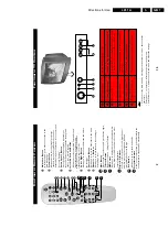
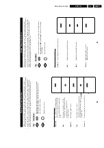
Antenna Connection
•
Connect the aerial plug to the antenna sock
et
¬¬¬¬¬
on the backco
ve
r.
•
Inser
t the mains plug into the wall sock
et.
Mains Connection
•
F
or cor
rect mains v
oltage
, r
e
fer to type stick
er at
the r
ear of the
TV set
•
Consult y
o
ur dealer if mains suppl
y is differ
ent.
Note
:
This diagram is not r
epr
esentativ
e of the
actual plug and sock
et.
Switching on the Set
•
P
ress the main po
w
er button to s
w
itch on/
off the
TV
.
•
If the set is on standb
y (indicator is r
ed),
pr
ess the
Po
w
e
r
button on the r
e
mote
contr
ol to s
w
itch on set.
75
Ω
g
P
REP
ARA
TION
Using the Remote Contr
o
l
•
Inser
t the cor
rect type of batteries into the
compar
tment.
•
Ensur
e the batteries ar
e placed in the right
dir
ection.
+
–
Summary of Contents for L01.1A
Page 48: ...Spare Parts List GB 88 L01 1A 10 ...
Page 78: ...56 L01 1A 7 Schematics and PWB s Layout PIP Panel Top View CL 16532010_010 eps 210301 ...
Page 79: ...Schematics and PWB s 57 L01 1A 7 Layout PIP Panel Bottom View CL 16532010_011 eps 210301 ...
Page 88: ...66 L01 1A 7 Schematics and PWB s Personal Notes Personal Notes ...


