Service Modes, Error Codes, and Fault Finding
5.
5.
Service Modes, Error Codes, and Fault Finding
Index:
1.
Test points.
2.
Service Modes.
3.
Problems and Solving Tips (related to CSM).
4.
ComPair
5.
Error Codes.
6.
The Blinking LED Procedure.
7.
Protections.
8.
Repair Tips.
5.1
Test Points
The chassis is equipped with test points printed on the circuit
board assemblies. These test points refer to the functional
blocks:
Table 5-1 Test Point Overview
The numbering is in a logical sequence for diagnostics. Always
start diagnosing within a functional block in the sequence of the
relevant test points for that block.
Perform measurements under the following conditions:
•
Service Default Alignment Mode.
•
Video: color bar signal.
•
Audio: 3 kHz left, 1 kHz right.
5.2
Service Modes
Service Default Alignment Mode (SDAM) offers several
features for the service technician, while the Customer Service
Mode (CSM) is used for communication between dealer and
customer.
There is also the option of using ComPair, a hardware interface
between a computer (see requirements) and the TV chassis. It
offers the ability of structured trouble shooting, error code
reading and software version readout for all chassis.
Requirements: To run ComPair on a computer (laptop or
desktop) requires, as a minimum, a 486 processor, Windows
3.1 and a CD-ROM drive. A Pentium Processor and Windows
95/98 are however preferred (see also paragraph 5.4).
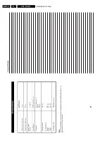
Table 5-2 SW Cluster
5.2.1
Service Default Alignment Mode (SDAM)
Purpose
•
To change option settings.
•
To create a predefined setting to get the same
measurement results as given in this manual.
•
To display / clear the error code buffer.
•
To override SW protections.
•
To perform alignments.
•
To start the blinking LED procedure.
Specifications
•
Tuning frequency: 61.25 MHz (channel 3) for NTSC-sets
(LATAM).
•
Color system: PAL-M for LATAM BI/TRI/FOUR-NORMA.
•
All picture settings at 50 % (brightness, color contrast,
hue).
•
Bass, treble and balance at 50 %; volume at 25 %.
•
All service-unfriendly modes (if present) are disabled, like:
–
(Sleep) timer,
–
Child/parental lock,
–
Blue mute,
–
Hotel/hospitality mode
–
Auto switch-off (when no “IDENT” video signal is
received for 15 minutes),
–
Skip / blank of non-favorite presets / channels,
–
Auto store of personal presets,
–
Auto user menu time-out.
•
Operation hours counter.
•
Software version.
•
Option settings.
•
Error buffer reading and erasing.
•
Software alignments.
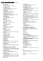
How to enter SDAM
Use one of the following methods:
•
Use a standard customer RC-transmitter and key in the
code 062596 directly followed by the “M” (menu) button or
•
Short jumper wires 9631 and 9641 on the mono carrier
(see Fig. 8-1) and apply AC power. Then press the power
button (remove the short after start-up).
•
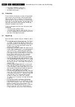
Caution: Entering SDAM by shorten wires 9631 and 9641
will override the +8V-protection. Do this only for a short
TEST POINT CIRCUIT
DIAGRAM
A1-A2-A3-..
AUDIO PROCESSING
A8,A9 / A11
C1-C2-C3-..
CONTROL
A7
F1-F2-F3-..
FRAME DRIVE & OUTPUT A3
I1-I2-I3-..
TUNER & IF
A4
L1-L2-L3-..
LINE DRIVE & OUTPUT
A2
P1-P2-P3-..
POWER SUPPLY
A1
S1-S2-S3-..
SYNCHRONISATION
A6
V1-V2-V3-..
VIDEO PROCESSING
A5,B1
SW Cluster Software
name
UOC type UOC Di-
versity
Special
Fea-
tures
L3LLS1
L01LS4 x.y TDA9599
(LS)
96K
ROM
Size
CC,
Stereo
dBx,
wide
screen ,
Dolby
EW
L3LLS2
L01LS5 x.y TDA9570
(LS)
55K
ROM
Size
CC,
Stereo
dBx
L3LLS3
L01LS3 x.y TDA9583
(LS)
64K
ROM
Size
CC,
Stereo
dBx,EW
L3LLN2
L01LN2 x.y TDA9570
(LS)
55K
ROM
Size
CC,
Stereo
non-
dBx
Abbreviations in Software name: L = Latam, M = Mono,
N = Stereo non-dBx and S = Stereo dBx.
Summary of Contents for L01.1L AC
Page 6: ...Directions for Use EN 6 L01 1L AC 3 3 Directions for Use 3 1 16 9 Sets ...
Page 7: ...Directions for Use EN 7 L01 1L AC 3 ...
Page 8: ...Directions for Use EN 8 L01 1L AC 3 ...
Page 9: ...Directions for Use EN 9 L01 1L AC 3 ...
Page 10: ...Directions for Use EN 10 L01 1L AC 3 ...
Page 11: ...Directions for Use EN 11 L01 1L AC 3 ...
Page 12: ...Directions for Use EN 12 L01 1L AC 3 ...
Page 13: ...Directions for Use EN 13 L01 1L AC 3 ...
Page 14: ...Directions for Use EN 14 L01 1L AC 3 ...
Page 15: ...Directions for Use EN 15 L01 1L AC 3 ...
Page 16: ...Directions for Use EN 16 L01 1L AC 3 Personal Notes ...
Page 17: ...Directions for Use EN 17 L01 1L AC 3 3 2 4 3 Sets Personal Notes ...
Page 42: ...Spare Parts List EN 82 L01 1L AC 10 10 Spare Parts List Not applicable yet ...
Page 43: ...Revision List EN 83 L01 1L AC 11 11 Revision List First release ...

