Service Modes, Error Codes, and Fault Finding
5.
4.
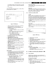
Select the STORE menu item.
Colors not correct / unstable picture
Check CSM line 5. Wrong color system installed. To change
the setting:
1.
Press the MENU button on the remote control.
2.
Select the INSTALLATION sub menu.
3.
Select and change the SYSTEM setting until picture and
sound are correct.
4.
Select the STORE menu item.
Picture too dark or too bright
Increase / decrease the BRIGHTNESS and / or the
CONTRAST value when:
•
The picture improves after you have pressed the “Smart
Picture” button on the remote control.
•
The picture improves after you have switched on the
Customer Service Mode
The new “Personal” preference value is automatically stored.
White line around picture elements and text
Decrease the SHARPNESS value when:
•
The picture improves after you have pressed the “Smart
Picture” button on the remote control.
The new “Personal” preference value is automatically stored.
Snowy picture
Check CSM line 5. If this line indicates “Not Tuned”, check the
following:
•
No or bad antenna signal. Connect a proper antenna
signal.
•
Antenna not connected. Connect the antenna.
•
No channel / pre-set is stored at this program number. Go
to the INSTALL menu and store a proper channel at this
program number.
•
The tuner is faulty (in this case the CODES line will contain
error number 10). Check the tuner and replace / repair if
necessary.
Snowy picture and/or unstable picture
•
A scrambled or decoded signal is received.
Black and white picture
Increase the COLOR value when:
•
The picture improves after you have pressed the “Smart
Picture” button on the remote control.
The new “Personal” preference value is automatically stored.
Menu text not sharp enough
Decrease the CONTRAST value when:
The picture improves after you have pressed the “Smart
Picture” button on the remote control.
The new “Personal” preference value is automatically stored.
5.3.2
Sound Problems
No sound or sound too loud (after channel change /
switching on)
Increase / decrease the VOLUME level when the volume is OK
after you switched on the CSM. The new “Personal” preference
value is automatically stored.
5.4
ComPair
5.4.1
Introduction
ComPair (Computer Aided Repair) is a service tool for Philips
Consumer Electronics products. ComPair is a further
development on the European DST (service remote control),
which allows faster and more accurate diagnostics. ComPair
has three big advantages:
•
ComPair helps you to quickly get an understanding on how
to repair the chassis in a short time by guiding you
systematically through the repair procedures.
•
ComPair allows very detailed diagnostics (on I2C level)
and is therefore capable of accurately indicating problem
areas. You do not have to know anything about I2C
commands yourself because ComPair takes care of this.
•
ComPair speeds up the repair time since it can
automatically communicate with the chassis (when the
microprocessor is working) and all repair information is
directly available. When ComPair is installed together with
the SearchMan electronic manual of the defective chassis,
schematics and PWBs are only a mouse click away.
5.4.2
Specifications
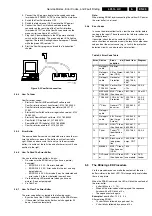
ComPair consists of a Windows based faultfinding program
and an interface box between PC and the (defective) product.
The ComPair interface box is connected to the PC via a serial
or RS232 cable.
In case of the L01 chassis, the ComPair interface box and the
TV communicate via a bi-directional service cable via the
service connector (located on the Main panel, see also figure
8-1 suffix D).
The ComPair faultfinding program is able to determine the
problem of the defective television. ComPair can gather
diagnostic information in two ways:
•
Automatic (by communication with the television):
ComPair can automatically read out the contents of the
entire error buffer. Diagnosis is done on I2C level. ComPair
can access the I2C bus of the television. ComPair can
send and receive I2C commands to the micro controller of
the television. In this way, it is possible for ComPair to
communicate (read and write) to devices on the I2C
busses of the TV-set.
•
Manually (by asking questions to you): Automatic
diagnosis is only possible if the micro controller of the
television is working correctly and only to a certain extends.
When this is not the case, ComPair will guide you through
the faultfinding tree by asking you questions (e.g. Does the
screen give a picture? Click on the correct answer: YES /
NO) and showing you examples (e.g. Measure test-point I7
and click on the correct oscillogram you see on the
oscilloscope). You can answer by clicking on a link (e.g.
text or a waveform picture) that will bring you to the next
step in the faultfinding process.
By a combination of automatic diagnostics and an interactive
question / answer procedure, ComPair will enable you to find
most problems in a fast and effective way.
Beside fault finding, ComPair provides some additional
features like:
•
Up- or downloading of pre-sets.
•
Managing of pre-set lists.
•
Emulation of the Dealer Service Tool (DST).
•
If both ComPair and SearchMan (Electronic Service
Manual) are installed, all the schematics and the PWBs of
the set are available by clicking on the appropriate
hyperlink. Example: Measure the DC-voltage on capacitor
C2568 (Schematic/Panel) at the Mono-carrier.
–
Click on the 'Panel' hyperlink to automatically show the
PWB with a highlighted capacitor C2568.
–
Click on the 'Schematic' hyperlink to automatically
show the position of the highlighted capacitor.
5.4.3
How To Connect ComPair
1.
First install the ComPair Browser software (see the Quick
Reference Card for installation instructions).
2.
Connect the RS232 interface cable between a free serial
(COM) port of your PC and the PC connector (marked with
“PC”) of the ComPair interface.
Summary of Contents for L01.1L AC
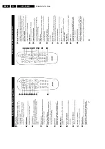
Page 6: ...Directions for Use EN 6 L01 1L AC 3 3 Directions for Use 3 1 16 9 Sets ...
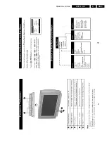
Page 7: ...Directions for Use EN 7 L01 1L AC 3 ...
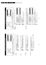
Page 8: ...Directions for Use EN 8 L01 1L AC 3 ...
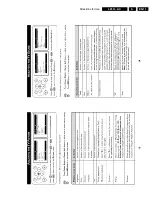
Page 9: ...Directions for Use EN 9 L01 1L AC 3 ...
Page 10: ...Directions for Use EN 10 L01 1L AC 3 ...
Page 11: ...Directions for Use EN 11 L01 1L AC 3 ...
Page 12: ...Directions for Use EN 12 L01 1L AC 3 ...
Page 13: ...Directions for Use EN 13 L01 1L AC 3 ...
Page 14: ...Directions for Use EN 14 L01 1L AC 3 ...
Page 15: ...Directions for Use EN 15 L01 1L AC 3 ...
Page 16: ...Directions for Use EN 16 L01 1L AC 3 Personal Notes ...
Page 17: ...Directions for Use EN 17 L01 1L AC 3 3 2 4 3 Sets Personal Notes ...
Page 42: ...Spare Parts List EN 82 L01 1L AC 10 10 Spare Parts List Not applicable yet ...
Page 43: ...Revision List EN 83 L01 1L AC 11 11 Revision List First release ...

