Alignments
8.
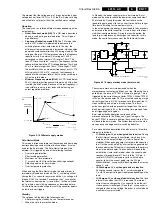
AGC (AGC take over point)
Set the external pattern generator to a color bar video signal
and connect the RF output to aerial input. Set amplitude to 10
mV and set frequency to 61.25 MHz (channel 3).
Connect a DC multimeter to pin 1 of the tuner (item 1000 on
the main chassis).
1.
Activate the SDAM.
2.
Go to the TUNER sub menu.
3.
Select AGC with the UP/DOWN cursor keys.
4.
Adjust the AGC-value (default value is 27) with the LEFT/
RIGHT cursor keys until the voltage at pin 1 of the tuner lies
between 3.8 and 2.3 V.
5.
Return to the SDAM via the MENU key and Switch the set
to STANDBY.
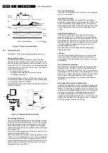
SL (Slicing Level)
Forced slicing level for vertical sync.
0 : slicing level dependent on noise detector
1 : fixed slicing level of 70%
8.3.3
White Tone
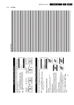
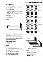
Figure 8-5 White tone alignment menu
In the WHITE TONE sub menu, the values of the black cut off
level can be adjusted. Normally, no alignment is needed for the
WHITE TONE. You can use the given default values.
The color temperature NORMAL RED, NORMAL GREEN and
NARMAL BLUE can be selected with the UP/DOWN RIGHT/
LEFT cursor keys. The value can be changed with the LEFT/
RIGHT cursor keys. After alignment, switch the set to standby,
in order to store the alignments value.
Default settings:
NORMAL (color temperature = 9600 K):
•
NORMAL R = 40
•
NORMAL G = 40
•
NORMAL B = 40
8.3.4
Geometry
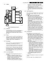
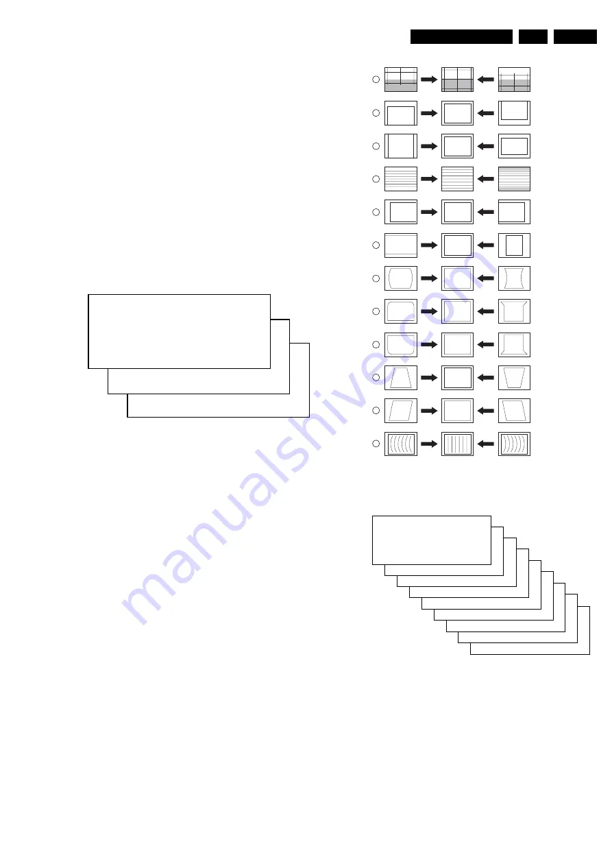
The geometry alignments menu contains several items to align
the set, in order to obtain a correct picture geometry.
Connect an external video pattern generator to the aerial input
of the TV-set and input a crosshatch test pattern. Set the
generator amplitude to at least 1 mV and set frequency to 61.25
MHz (channel 3).
1.
Set 'Smart Picture' to NATURAL (or MOVIES).
2.
Activate the SDAM menu (see chapter 5).
3.
Go to the GEOMETRY sub menu.
4.
Choose HORIZONTAL or VERTICAL alignment
Now the following alignments can be performed:
Figure 8-6 Geometry alignments
Figure 8-7 Horizontal alignment menu
Horizontal:
•
Horizontal Parallelogram (HP)
Align straight vertical lines in the top and the bottom;
vertical rotation around the center.
•
Horizontal Bow (HB)
Align straight horizontal lines in the top and the bottom;
horizontal rotation around the center.
•
Horizontal Shift (HSH)
Align the horizontal center of the picture to the horizontal
center of the CRT.
NORMAL BLUE
XX
NORMAL GREEN
XX
S
NORMAL RED
XX
CL 26532046_005.eps
040402
CL 16532044_022.eps
140501
1
2
3
4
5
6
7
8
9
10
11
12
VERT. SLOPE
VERT. SHIFT
VERT. AMPLITUDE
V.S-CORRECTION
HOR. SHIFT
HOR. AMPLITUDE
E/W PARABOLE
UPPER E/W CORNER
LOWER E/W CORNER
E/W TRAPEZIUM
HOR. PARALLELOGRAM
HOR. BOW
HP
XX
HB
XX
HSH
XX
EWW
XX
EWP
XX
OCP
XX
LCP
XX
EWT
XX
S
HOR IZONTAL
>
VERTICAL
>
CL 26532046_006.eps
040402
Summary of Contents for L01.1L AC
Page 6: ...Directions for Use EN 6 L01 1L AC 3 3 Directions for Use 3 1 16 9 Sets ...
Page 7: ...Directions for Use EN 7 L01 1L AC 3 ...
Page 8: ...Directions for Use EN 8 L01 1L AC 3 ...
Page 9: ...Directions for Use EN 9 L01 1L AC 3 ...
Page 10: ...Directions for Use EN 10 L01 1L AC 3 ...
Page 11: ...Directions for Use EN 11 L01 1L AC 3 ...
Page 12: ...Directions for Use EN 12 L01 1L AC 3 ...
Page 13: ...Directions for Use EN 13 L01 1L AC 3 ...
Page 14: ...Directions for Use EN 14 L01 1L AC 3 ...
Page 15: ...Directions for Use EN 15 L01 1L AC 3 ...
Page 16: ...Directions for Use EN 16 L01 1L AC 3 Personal Notes ...
Page 17: ...Directions for Use EN 17 L01 1L AC 3 3 2 4 3 Sets Personal Notes ...
Page 42: ...Spare Parts List EN 82 L01 1L AC 10 10 Spare Parts List Not applicable yet ...
Page 43: ...Revision List EN 83 L01 1L AC 11 11 Revision List First release ...

