Circuit Description
9.
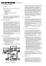
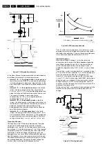
Figure 9-7 QR-mode time intervals
In the Quasi-Resonant mode each period can be divided into
four different time intervals, in chronological order:
•
Interval 1: t0 < t < t1 primary stroke. At the beginning of
the first interval, the MOSFET is switched 'on' and energy
is stored in the primary inductance (magnetization). At the
end, the MOSFET is switched 'off' and the second interval
starts.
•
Interval 2: t1 < t < t2 commutation time. In the second
interval, the drain voltage will rise from almost zero to
V_in+n•(V_out+V_f). V_f is the forward voltage drop of de
diode that will be omitted from the equations from now on.
The current will change its positive derivative,
corresponding to V_in/L_p, to a negative derivative,
corresponding to -n•(V_out/L_p).
•
Interval 3: t2 < t < t3 secondary stroke. In the third
interval, the stored energy is transferred to the output, so
the diode starts to conduct and the inductive current Il will
decrease. In other words, the transformer will be
demagnetized. When the inductive current has become
zero the next interval begins.
•
Interval 4: t3 < t < t00 resonance time. In the fourth
interval, the energy stored in the drain capacitor C_d will
start to resonate with the inductance L_p. The voltage and
current waveforms are sinusoidal waveforms. The drain
voltage will drop from V_in+(n•V_out) to V_in-(n•V_out).
Frequency Behavior
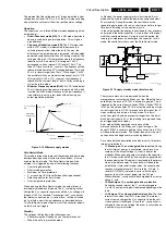
The frequency in the QR-mode is determined by the power
stage and is not influenced by the controller (important
parameters are L_p and C_d). The frequency varies with the
input voltage V_in and the output power P_out. If the required
output power increases, more energy has to be stored in the
transformer. This leads to longer magnetizing t_prim and
demagnetizing t_sec times, which will decrease the frequency.
See the frequency versus output power characteristics below.
The frequency characteristic is not only output power-, but also
input voltage dependent. The higher the input voltage, the
smaller t_prim, so the higher the frequency will be.
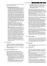
Figure 9-8 QR frequency behavior
Point P1 is the minimum frequency f_min that occurs at the
specified minimum input voltage and maximum output power
required by the application. Of course, the minimum frequency
has to be chosen above the audible limit (>20 kHz).
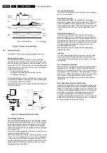
Start-Up Sequence
When the rectified AC voltage V_in (via the center tap
connected to pin 8) reaches the Mains dependent operation
level (Mlevel: between 60 and 100 V), the internal 'Mlevel
switch' will be opened and the start-up current source is
enabled to charge capacitor C2521 at the V_cc pin as shown
below.
The 'soft start' switch is closed when the V_cc reaches a level
of 7 V and the 'soft start' capacitor C_ss (C2522, between pin
5 and the sense resistor R3526), is charged to 0.5 V.
Once the V_cc capacitor is charged to the start-up voltage
V_start (11 V), the IC starts driving the MOSFET. Both internal
current sources are switched 'off' after reaching this start-up
voltage. Resistor R_ss (3524) will discharge the 'soft start'
capacitor, such that the peak current will slowly increase. This
to prevent 'transformer rattle'.
During start-up, the V_cc capacitor will be discharged until the
moment that the primary auxiliary winding takes over this
voltage.
Figure 9-9 Start-up behavior
V
IN
V
GATE
V
D
n
⋅
V
OUT
I
L
C
D
C
OUT
D
L
P
C
IN
0
Demagneti-
zation
V
GATE
V
D
I
L
0
Magnetization
t
1
t
2
t
3
t
00
T
t
0
1
2
3
4
Valley
n
⋅
V
OUT
V
IN
CL 16532020_084.eps
110401
V
IN_MAX
P
OUT_MIN
P
OUT_MAX
power
switching
frequency
f
MIN
f
MAX
V
IN_MIN
P1
P2
QR frequency characteristics at different input voltages
CL 16532020_077.eps
100401
0.5V
+
-
I
L
R
SENSE
I
SS
V
OCP
R
SS
C
SS
soft start
V
IN
8
5
1
Mlevel
I
in(Vcc)
V
SENSE
2
C
Vcc
V
CC
Charging of V
CC
capacitor
taken over by the winding
V
(start)
=11V
C
Vcc
charged
by current
V
OUT
V
GATE
V
CC
V
SENSE
I
L
τ
= R
SS
⋅
C
SS
≈
7V
Start-up sequence
CL 16532020_078.eps
110401
Summary of Contents for L01.1L AC
Page 6: ...Directions for Use EN 6 L01 1L AC 3 3 Directions for Use 3 1 16 9 Sets ...
Page 7: ...Directions for Use EN 7 L01 1L AC 3 ...
Page 8: ...Directions for Use EN 8 L01 1L AC 3 ...
Page 9: ...Directions for Use EN 9 L01 1L AC 3 ...
Page 10: ...Directions for Use EN 10 L01 1L AC 3 ...
Page 11: ...Directions for Use EN 11 L01 1L AC 3 ...
Page 12: ...Directions for Use EN 12 L01 1L AC 3 ...
Page 13: ...Directions for Use EN 13 L01 1L AC 3 ...
Page 14: ...Directions for Use EN 14 L01 1L AC 3 ...
Page 15: ...Directions for Use EN 15 L01 1L AC 3 ...
Page 16: ...Directions for Use EN 16 L01 1L AC 3 Personal Notes ...
Page 17: ...Directions for Use EN 17 L01 1L AC 3 3 2 4 3 Sets Personal Notes ...
Page 42: ...Spare Parts List EN 82 L01 1L AC 10 10 Spare Parts List Not applicable yet ...
Page 43: ...Revision List EN 83 L01 1L AC 11 11 Revision List First release ...


