Circuit Description
9.
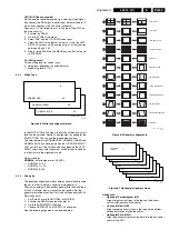
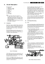
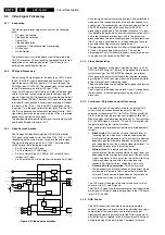
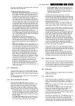
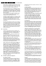
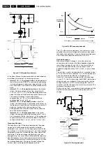
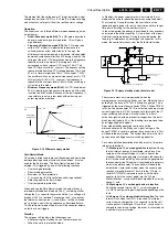
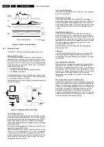
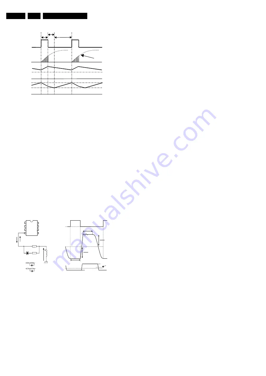
Figure 9-12 Burst mode waveforms
9.6.3
Protection Events
The SMPS IC 7520 has the following protection features:
Demagnetization sense
This feature guarantees discontinuous conduction mode
operation in every situation. The oscillator will not start a new
primary stroke until the secondary stroke has ended. This is to
ensure that FET 7521 will not turn on until the demagnetization
of transformer 5520 is complete. The function is an additional
protection feature against:
•
Saturation of the transformer.
•
Damage of the components during initial start-up.
•
An overload of the output.
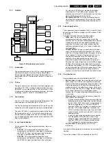
The demag(netization) sense is realized by an internal circuit
that guards the voltage (V_demag) at pin 4 that is connected to
V_cc winding by resistor R1 (R3522).
The figure below shows the circuit and the idealized waveforms
across this winding.
Figure 9-13 Demagnetization protection
Over Voltage Protection
The Over Voltage Protection ensures that the output voltage
will remain below an adjustable level. This works by sensing
the auxiliary voltage via the current flowing into pin 4 (DEM)
during the secondary stroke. This voltage is a well-defined
replica of the output voltage. Any voltage spikes are averaged
by an internal filter.
If the output voltage exceeds the OVP trip level, the OVP circuit
switches the power MOSFET 'off'.
Next, the controller waits until the 'under voltage lock out' level
(UVLO =
±
9 V) is reached on pin 1 (V_cc). This is followed by
a safe restart cycle, after which switching starts again. This
process is repeated as long as the OVP condition exists. The
output voltage at which the OVP function trips, is set by the
demagnetization resistor R3522.
Over Current Protection
The internal OCP protection circuit limits the 'sense' voltage on
pin 5 to an internal level.
Over Power Protection
During the primary stroke, the rectified AC input voltage is
measured by sensing the current drawn from pin 4 (DEM). This
current is dependent on the voltage on pin 9 of transformer
5520 and the value of R3522. The current information is used
to adjust the peak drain current, which is measured via pin
I_sense.
Short Winding Protection
If the 'sense' voltage on pin 5 exceeds the short winding
protection voltage (0.75 V), the converter will stop switching.
Once V_cc drops below the UVLO level, capacitor C2521 will
be recharged and the supply will start again. This cycle will be
repeated until the short circuit is removed (safe restart mode).
The short winding protection will also protect in case of a
secondary diode short circuit.
This protection circuit is activated after the leading edge
blanking time (LEB).
LEB time
The LEB (Leading Edge Blanking) time is an internally fixed
delay, preventing false triggering of the comparator due to
current spikes. This delay determines the minimum 'on' time of
the controller.
Over Temperature protection
When the junction temperature exceeds the thermal shutdown
temperature (typ. 140 deg. C), the IC will disable the driver.
When the V_cc voltage drops to UVLO, the V_cc capacitor will
be recharged to the V(start) level. If the temperature is still too
high, the V_cc voltage will drop again to the UVLO level (Safe-
Restart mode). This mode will persist until the junction
temperature drops 8 degrees typically below the shutdown
temperature.
Mains dependent operation enabling level
To prevent the supply from starting at a low input voltage, which
could cause audible noise, a mains detection is implemented
(Mlevel). This detection is provided via pin 8, which detects the
minimum start-up voltage between 60 and 100 V. As previous
mentioned, the controller is enabled between 60 and 100 V.
An additional advantage of this function is the protection
against a disconnected buffer capacitor (C_in). In this case, the
supply will not be able to start-up because the V_cc capacitor
will not be charged to the start-up voltage.
V
(start)
V
(UVLO)
V
CC
V
STAB
I
L
Active/
inactive
t1
t2
t3
V
µ
C
Soft start
Burst mode waveforms
CL 16532020_082.eps
100401
R
1
R
2
D
V
CC
winding
I
(ovp)(demag)
I
(opp)(demag)
Demag
4
Ctrl
Gnd
Vcc
Drain
HVS
Driver
Sense
3
2
1
5
6
7
8
configuration
A
B
0V
OUT
S
Vcc
V
N
N
⋅
IN
P
Vcc
V
N
N
⋅
Demagnetization
V
GATE
V
WINDING
Magnetization
V
demag
Comparator
threshold
V
demag
0.7V
0V
-0.25V
Summary of Contents for L01.1L AC
Page 6: ...Directions for Use EN 6 L01 1L AC 3 3 Directions for Use 3 1 16 9 Sets ...
Page 7: ...Directions for Use EN 7 L01 1L AC 3 ...
Page 8: ...Directions for Use EN 8 L01 1L AC 3 ...
Page 9: ...Directions for Use EN 9 L01 1L AC 3 ...
Page 10: ...Directions for Use EN 10 L01 1L AC 3 ...
Page 11: ...Directions for Use EN 11 L01 1L AC 3 ...
Page 12: ...Directions for Use EN 12 L01 1L AC 3 ...
Page 13: ...Directions for Use EN 13 L01 1L AC 3 ...
Page 14: ...Directions for Use EN 14 L01 1L AC 3 ...
Page 15: ...Directions for Use EN 15 L01 1L AC 3 ...
Page 16: ...Directions for Use EN 16 L01 1L AC 3 Personal Notes ...
Page 17: ...Directions for Use EN 17 L01 1L AC 3 3 2 4 3 Sets Personal Notes ...
Page 42: ...Spare Parts List EN 82 L01 1L AC 10 10 Spare Parts List Not applicable yet ...
Page 43: ...Revision List EN 83 L01 1L AC 11 11 Revision List First release ...

