Circuit Description
9.
9.7
Control
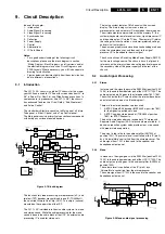
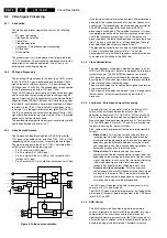
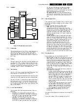
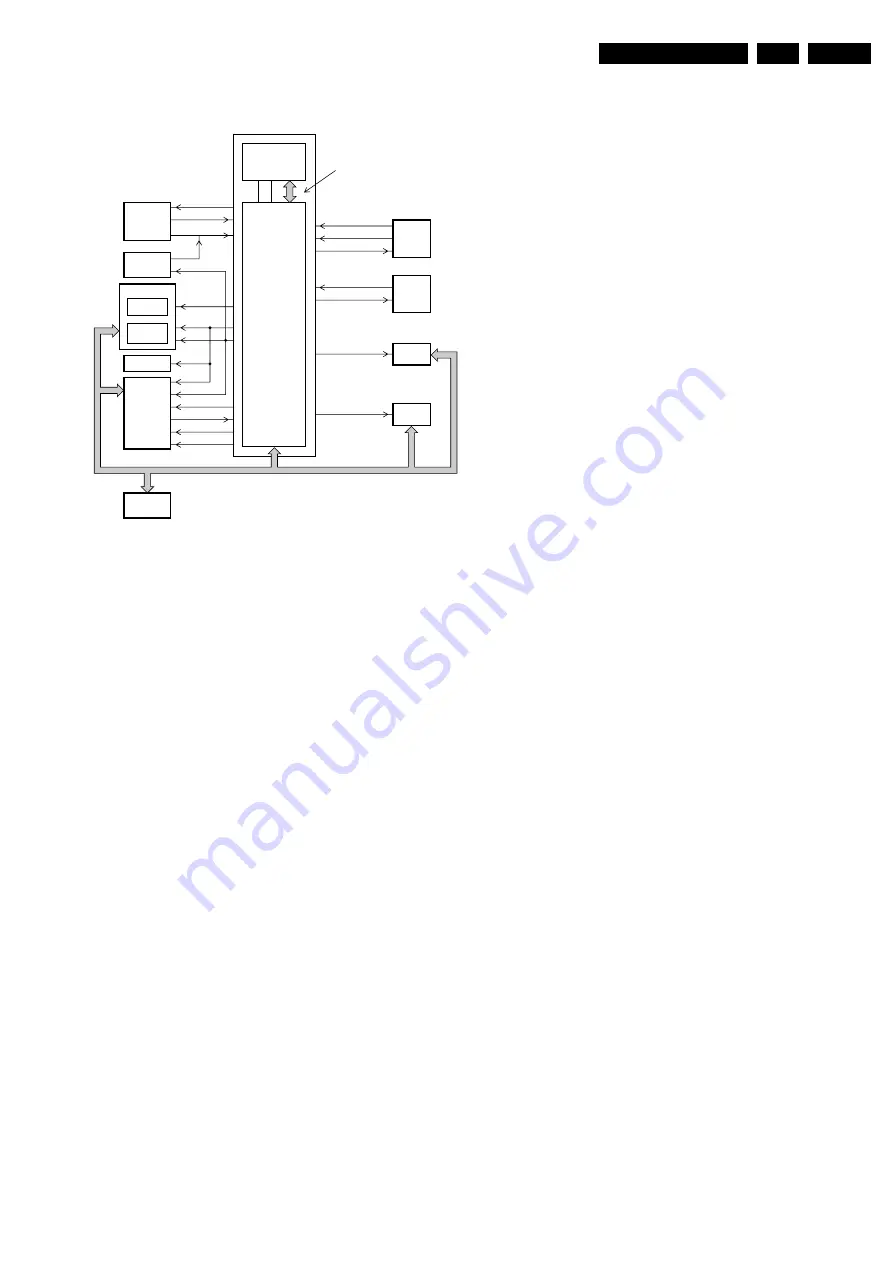
Figure 9-14 Block diagram set control
9.7.1
Introduction
The microprocessor part of the UOC, has the complete control
and teletext on board. User menu, Service Default Mode,
Service Alignment Mode and Customer Service Mode are
generated by the uP. Communication to other ICs is done via
the I
2
C-bus.
9.7.2
I
2
C-Bus
The main control system, which consists of the microprocessor
part of the UOC (7200), is linked to the external devices (tuner,
NVM, MSP, etc) by means of the I
2
C-bus. An internal I
2
C-bus
is used to control other signal processing functions, like video
processing, sound IF, vision IF, synchronization, etc.
9.7.3
User Interface
The 'L01.1L AC' uses a remote control with RC5 protocol. The
incoming signal is connected to pin 67 of the UOC.
The 'Top Control' keyboard, connected to UOC pin 80, can also
control the set. Button recognition is done via a voltage divider.
The front LED (6691) is connected to an output control line of
the microprocessor (pin 5). It is activated to provide the user
information about whether or not the set is working correctly
(e.g., responding to the remote control, normal operation (USA
only) or fault condition)
9.7.4
In- and Output Selection
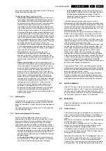
For the control of the input and output selections, there are
three lines:
•
STATUS1. This signal provides information to the
microprocessor on whether a video signal is available on
the SCART1 AV input and output port (only for Europe).
This signal is not connected in NAFTA sets.
•
STATUS2. This signal provides information to the
microprocessor on whether a video signal is available on
the SCART2 AV input and output port (only for Europe).
For sets with an SVHS input it provides the additional
information if a Y/C or CVBS source is present. The
presence of an external Y/C source makes this line 'high'
while a CVBS source makes the line 'low'.
•
SEL-MAIN-FRNT-RR. This is the source select control
signal from the microprocessor. This control line is under
user control or can be activated by the other two control
lines.
9.7.5
Power Supply Control
The microprocessor part is supplied with 3.3 V and 3.9 V both
derived from the 'MainAux' voltage via a 3V3 stabilizer (7560)
and a diode.
Two signals are used to control the power supply:
•
Stdby_con. This signal is generated by the
microprocessor when over-current takes place at the
'MainAux' line. This is done to enable the power supply into
standby burst mode, and to enable this mode during a
protection. This signal is 'low' under normal operation
conditions and goes to 'high' (3.3 V) under 'standby' and
'fault' conditions.
•
POWER_DOWN. This signal is generated by the power
supply. Under normal operating conditions, this signal is
'high' (3.3 V). During 'standby' mode, this signal is a pulse
train of approx. 10 Hz and a 'high' duration of 5 ms. It is
used to give information to the UOC about the fault
condition in the Audio amplifier supply circuit. This
information is generated by sensing the current on the
'MainAux' line (using voltage drop across R3564 to trigger
TS7562). This signal goes 'low' when the DC-current on
the 'MainAux' line exceeds 1.6 - 2.0 A. It is also used to give
an early warning to the UOC about a power failure. Then
the information is used to mute the sound amplifier to
prevent a switch off noise and to solve the switch-off spot.
9.7.6
Protection Events
Several protection events are controlled by the UOC:
•
BC protection, to protect the picture tube from a too high
beam current. The UOC has the capability of measuring
the normal back level current during the vertical flyback. So
if for some reason the CRT circuit is malfunctioning (i.e.
high beam current), the normal black current will be out of
the 75 uA range, and the UOC will trigger the power supply
to shut down. However, this is a high beam-current
situation, the TV screen will be bright white before the set
is shut down.
•
E/W protection, two protection mechanisms are built in,
over-current and over-voltage.
–
In case of over-current due to defective parts in the line
deflection output stage, a high current will flow through
resistors 3405//3406. If this current is large enough to
create a voltage drop of 0.7 V across 3405//3406,
transistor TS7606 (in A7 diagram) will conduct and pin
80 of the UOC will be pulled down. Thereafter, the
UOC will shut down the power supply. In case of further
current increase, the fused resistor 3411 is built-in for
double protection.
–
In case of a high voltage appearing across capacitor
2401 (dependent of the tube size), which is high
enough to trigger zener diode 6401 into conduction,
transistor TS7606 (in A7 diagram) will conduct and
UOC is triggered to shut down the power supply.
•
I
2
C protection, to check whether all I
2
C ICs are
functioning.
In case one of these protections is activated, the set will go into
'standby'.
The 'on' and 'standby' LEDs are controlled via the UOC.
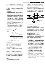
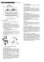
CL 16532016_015.eps
220301
Signal
Processing
User
Interface
uP - Control
LED
PANORAMA
PANORAMA
BUZZ
BASS
TREBLE/Tilt
ITV-DATA-OUT
ITV-DATA-IN
ITV-CLOCK
RESET
VOLUME/
MUTE
IR
KEYBOARD/
(EW protection
STATUS 1
STATUS 2
SEL-MAIN-FRNT-RR
internal I2C Bus
Deflection
16:9
Expansion
Slot
I/O
POWER_DOWN
STBY_CON
Power
Supply
WRITE Enable
NVM
SEL-IF-LL/M-TRAP
I2C Bus
Tuner / IF
Tilt
ITV
or
Pip
Amplifier
Processing
Sound
Summary of Contents for L01.1L AC
Page 6: ...Directions for Use EN 6 L01 1L AC 3 3 Directions for Use 3 1 16 9 Sets ...
Page 7: ...Directions for Use EN 7 L01 1L AC 3 ...
Page 8: ...Directions for Use EN 8 L01 1L AC 3 ...
Page 9: ...Directions for Use EN 9 L01 1L AC 3 ...
Page 10: ...Directions for Use EN 10 L01 1L AC 3 ...
Page 11: ...Directions for Use EN 11 L01 1L AC 3 ...
Page 12: ...Directions for Use EN 12 L01 1L AC 3 ...
Page 13: ...Directions for Use EN 13 L01 1L AC 3 ...
Page 14: ...Directions for Use EN 14 L01 1L AC 3 ...
Page 15: ...Directions for Use EN 15 L01 1L AC 3 ...
Page 16: ...Directions for Use EN 16 L01 1L AC 3 Personal Notes ...
Page 17: ...Directions for Use EN 17 L01 1L AC 3 3 2 4 3 Sets Personal Notes ...
Page 42: ...Spare Parts List EN 82 L01 1L AC 10 10 Spare Parts List Not applicable yet ...
Page 43: ...Revision List EN 83 L01 1L AC 11 11 Revision List First release ...


