Circuit Descriptions, Abbreviation List, and IC Data Sheets
9.
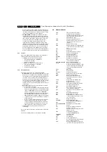
done to enable the power supply into standby burst mode,
and to enable this mode during a protection. This signal is
‘low’ under normal operation conditions and goes to ‘high’
(3.3 V) under ‘standby’ and ‘fault’ conditions.
•
POWER_DOWN
This signal is generated by the power
supply. Under normal operating conditions this signal is
‘high’ (3.3 V). During ‘standby’ mode, this signal is a pulse
train of approx. 10 Hz and a ‘high’ duration of 5 ms. It is
used to give information to the UOC about the fault
condition in the Audio amplifier supply circuit. This
information is generated by sensing the current on the
‘MainAux’ line (using voltage drop across R3564 to trigger
TS7562). This signal goes ‘low’ when the DC-current on
the ‘MainAux’ line exceeds 1.6 - 2.0 A. It is also used to
give an early warning to the UOC about a power failure.
Then the information is used to mute the sound amplifier to
prevent a switch off noise and to solve the switch-off spot.
9.7.7
Tuner IF
Pin 3 of the UOC (SEL-IF-LL’_M-TRAP), is an output pin to
switch the SAW-filter to the appropriate system.
•
If UOC pin 3 is ‘low’, the selected system is:
–
West Europe: PAL B/G, I, SECAM L/L’
–
East Europe: PAL B/G
–
Asia Pacific: NTSC M
•
If UOC pin 3 is ‘high’, the selected system is:
–
West Europe: SECAM L’, L’-NICAM
–
East Europe: PAL D/K
–
Asia Pacific: PAL B/G, D/K, I
9.7.8
Protection Events
Several protection events are controlled by the UOC:
•
BC protection
, to protect the picture tube from a too high
beam current. The UOC has the capability of measuring
the normal back level current during the vertical flyback. So
if for some reason the CRT circuit is malfunctioning (i.e.
high beam current), the normal black current will be out of
the 75
µ
A range, and the UOC will trigger the power supply
to shut down. However, this is a high beam-current
situation, the TV screen will be bright white before the set
is shut down.
•
E/W protection
, two protection mechanisms are built in,
over-current and over-voltage.
–
In case of over-current due to defective parts in the line
deflection output stage, a high current will flow through
resistors 3405//3406. If this current is large enough to
create a voltage drop of 0.7 V across 3405//3406,
transistor TS7606 (in A7 diagram) will conduct and pin
80 of the UOC will be pulled down. Thereafter, the
UOC will shut down the power supply. In case of further
current increase, the fused resistor 3411 is built-in for
double protection.
–
In case of a high voltage appearing across capacitor
2401 (dependent of the tube size), which is high
enough to trigger zener diode 6401 into conduction,
transistor TS7606 (in A7 diagram) will conduct and
UOC is triggered to shut down the power supply.
•
I
2
C protection
, to check whether all I
2
C IC's are
functioning.
In case one of these protections is activated, the set will go into
‘standby’.
The ‘on’ and ‘standby’ LEDs are controlled via the UOC.
9.8
Abbreviation list
2CS
2 Carrier (or Channel) Stereo
ACI
Automatic Channel Installation:
algorithm that installs TV sets directly
from cable network by means of a
predefined TXT page
ADC
Analogue to Digital Converter
AFC
Automatic Frequency Control: control
signal used to tune to the correct
frequency
AFT
Automatic Fine Tuning
AGC
Automatic Gain Control: algorithm that
controls the video input of the feature
box
AM
Amplitude Modulation
AP
Asia Pacific
AR
Aspect Ratio: 4 by 3 or 16 by 9
ATS
Automatic Tuning System
AV
External Audio Video
AVL
Automatic Volume Level
BC-PROT
Beam Current Protection
BCL
Beam Current Limitation
B/G
Monochrome TV system. Sound
carrier distance is 5.5 MHz
BLC-INFORMATION
Black current information
BTSC
Broadcast Television Standard
Committee. Multiplex FM stereo sound
system, originating from the USA and
used e.g. in LATAM and AP-NTSC
countries
B-TXT
Blue teletext
CC
Closed Caption
ComPair
Computer aided rePair
CRT
Cathode Ray Tube or picture tube
CSM
Customer Service Mode
CTI
Colour Transient Improvement:
manipulates steepness of chroma
transients
CVBS
Composite Video Blanking and
Synchronisation
DAC
Digital to Analogue Converter
DBE
Dynamic Bass Enhancement: extra
low frequency amplification
DBX
Dynamic Bass Expander
D/K
Monochrome TV system. Sound
carrier distance is 6.5 MHz
DFU
Direction For Use: description for the
end user
DNR
Dynamic Noise Reduction
DSP
Digital Signal Processing
DST
Dealer Service Tool: special remote
control designed for dealers to enter
e.g. service mode
DVD
Digital Versatile Disc
EEPROM
Electrically Erasable and
Programmable Read Only Memory
EHT
Extra High Tension
EHT-INFORMATION
Extra High Tension information
EU
Europe
EW
East West, related to horizontal
deflection of the set
EXT
External (source), entering the set via
SCART or Cinch
FBL
Fast Blanking: DC signal
accompanying RGB signals
FILAMENT
Filament of CRT
FLASH
Flash memory
FM
Field Memory
FM
Frequency Modulation
HA
Horizontal Acquisition: horizontal sync
pulse coming out of the HIP
HFB
Horizontal Flyback Pulse: horizontal
sync pulse from large signal deflection


