Directions for Use
3.
R
EMOTE
C
ONTROL
B
UTTON
D
ESCRIPTIONS
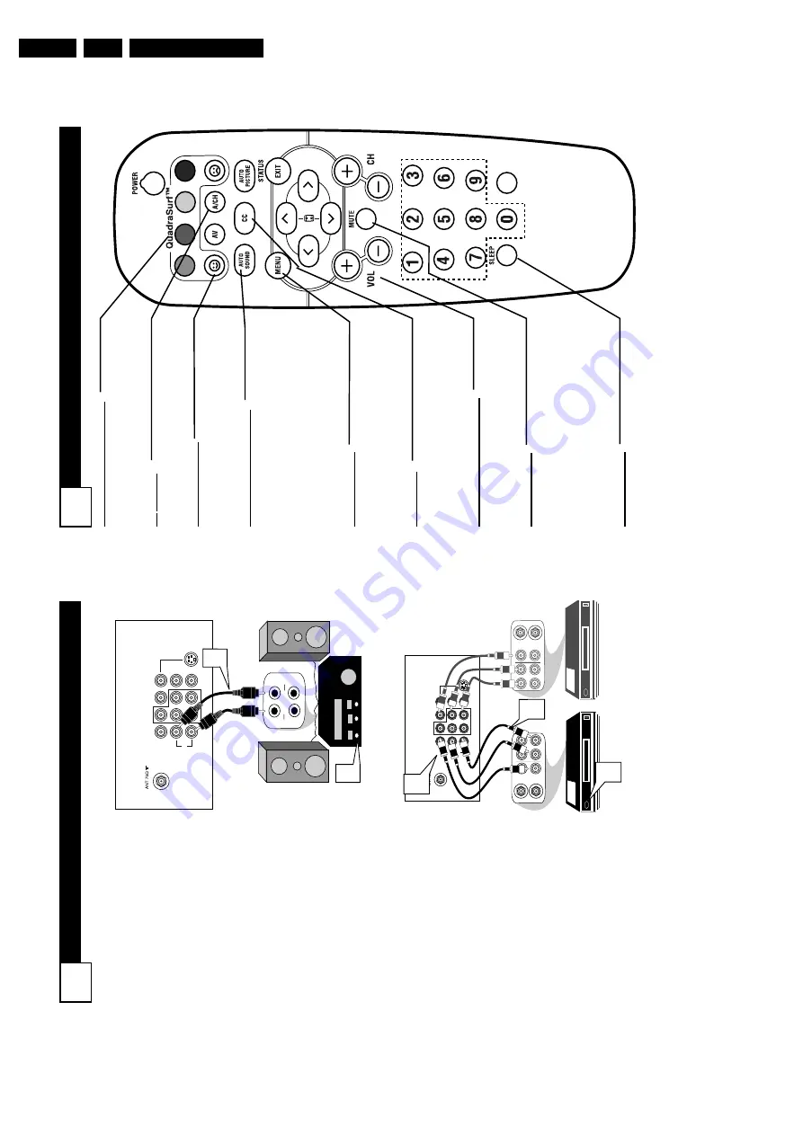
9
QUADRASURF
Buttons
(Red, Green,
Y
ellow
, Blue)
Allows you to
store and surf up to 10 channels you choose for each colored button.
A
V
Button
Press to select an accessory signal input from the front
A
V
Inputs.
SMILEY
Button
Press to add channels to the “QuadraSurf” lists.
W
orks with all col-
ored buttons.
AUT
O SOUND Button
Press repeatedly to choose from dif
ferent
factory pre-defined sound settings. Choose from Personal (how you set the Sound Menu options),
V
oice (for pro-
gramming with speaking only), Music (for musical type programs such as con- certs), or
Theatre (used when watching
movies).
MENU
Button
Press to display the on-screen menu.
Also
can be used to back out of the on-screen menu until it disappears from the
TV’
s
screen.
CC Button Press to activate the Closed Captioning options. Repeatedly pressing the CC but- ton will scroll the available options on the TV
screen.
V
OL(ume) + or
- Buttons
Press the
VOL
+ button to increase the
TV’
s sound level. Press the
VOL
– button
to decrease the
TV’
s sound level.
MUTE Button Press the mute button to eliminate the sound being heard from the
TV
. “MUTE”
will be displayed on the
TV’
s screen.
Press again to restore the
TV’
s volume to
it’
s previous level. pressing this button for
3-4 seconds will activate the Demo Mode. (See panel 30 for more details.)
SLEEP
Button
Press the Sleep button to set the
TV
to
automatically turn itself of
f after a set
period of time. Press repeatedly to select 15, 30, 45, 60, 90, 120, 180, or 240 min- utes.
VOL
M
ONITOR
O
UT
(
PUT
) C
ONNECTIONS
8
T
he
Audio/V
ideo (Monitor) Output
jacks ar
e gr
eat for r
ecor
ding with
a VCR or used to connect an exter-
nal audio system for better sound
repr
oduction.
A
UDIO SY
STEM
CONNECTION:
1
Connect one end of the
R(ight) and L(eft)
AUDIO
(Monitor
Out)
jacks on the
TV
to the R and L
audio input jacks
on your amplifier or sound sys-
tem. Set the audio system’
s vol-
ume to a normal listening level.
2
T
urn the
TV
and audio sys-
tem ON.
T
o
adjust the volume
on the audio system, you will
need to change the volume at
the external audio system, not
the television.
SECOND VCR
CONNECTION:
NOTE:
Refer to panel number 4 for
the proper hookup of the first
VCR.
Follow the instructions on how to
tune to the
A
V
1
channel to view a
pre-recorded tape.
The following steps allow you to
connect a second
VCR to r
ecord
the pr
ogram while your
watching
it.
3
Connect one end of the yellow
V
ideo Cable
to the Monitor
Out
VIDEO plug. Connect the
other end to the
VIDEO
IN plug
on the second
VCR.
4
Connect one end of the r
ed
and white
Audio cable
from
the Monitor Out
AUDIO L
and
R plugs on the
TV
to the
AUDIO IN plugs on the
VCR.
5
T
urn the Second
VCR ON,
insert a
VHS tape and it’
s
ready to record what’
s being
viewed on the
TV
screen.
L/Mono
Monitor out
VIDEO
S-VIDEO
A
V1 in
Y
Pb
Pr
A
V2 in
AUDIO
R
COMPONENT
VIDEO INPUT
A
U
X
/T
V
IN
P
U
T
P
H
O
N
O IN
P
UT
R
L
1
2
Back of
TV
Audio Cables
(Red and
White)
L/Mono
Monitor out
VIDEO
S-VIDEO
A
V1 in
Y
Pb
Pr
AV
2
i
n
AUDIO
R
COMPONENT
VIDEO INPUT
ANTENNA
OUT
ANTENNA
IN
VIDEO
AUDIO
IN
IN
OUT
OUT
L
R
ANTENNA
OUT
ANTENNA
IN
VIDEO
AUDIO
IN
IN
OUT
OUT
R
L
3
4
5
Back of
TV
Audio
Cables
1st VCR
(refer to panel 4 for
proper connection)
V
ideo
Cable
2nd
VCR with
Audio and
V
ideo Input Jacks
SECOND VCR
CONNECTION:
A
UDIO SY
STEM CONNECTION:
Summary of Contents for L04LAA
Page 36: ...Service Modes Error Codes and Fault Finding EN 36 L04L AA 5 E_06532_012 eps 130204 ...
Page 58: ...58 L04L AA 7 Circuit Diagrams and PWB Layouts Layout Mono Carrier Part 1 Bottom Side Part 1 ...
Page 93: ...Spare Parts List EN 93 L04L AA 10 10 Spare Parts List Not applicable ...
Page 94: ...Revision List EN 94 L04L AA 11 11 Revision List First release ...


