Technical Specifications, Connections, and Chassis Overview
1.
1.
Technical Specifications, Connections, and Chassis Overview
Notes:
•
Described specifications are valid for the whole (LATAM)
product range.
•
Figures below can deviate slightly from the actual situation,
due to different set executions.
1.1
Technical Specifications
1.1.1
Reception
Display type
:
CRT-DV-SF
Screen size
:
25” (63 cm), 4:3
:
28” (70 cm), 16:9
:
29” (72 cm), 4:3
:
32” (82 cm), 16:9
Tuning system
:
PLL
Color systems
:
NTSC M, or
:
TriNorma
Sound systems
:
BTSC, or
:
BTSC + SAP
Channel selections
:
181, full cable
IF picture carrier
:
45.75 MHz
Aerial input
:
75 ohm, F-type
A/V Connections
:
PAL B/G (pb)
1.1.2
Miscellaneous
Audio output:
:
2 x 5 W
:
2 x 10 W
Power supply:
- Mains voltage range
:
90 - 276 V_ac
- Mains frequency
:
50 / 60 Hz
Ambient conditions:
- Temperature range
:
+5 to +45 deg. C
- Maximum humidity
:
90% R.H.
Power consumption:
- Normal operation
:
from 56 W (25”)
:
to 70 W (32”)
- Standby
:
< 1 W
1.2
Connections
Note: The following connector color abbreviations are used
(acc. to DIN/IEC 757): Bk= Black, Bu= Blue, Gn= Green, Gy=
Grey, Rd= Red, Wh= White, Ye= Yellow.
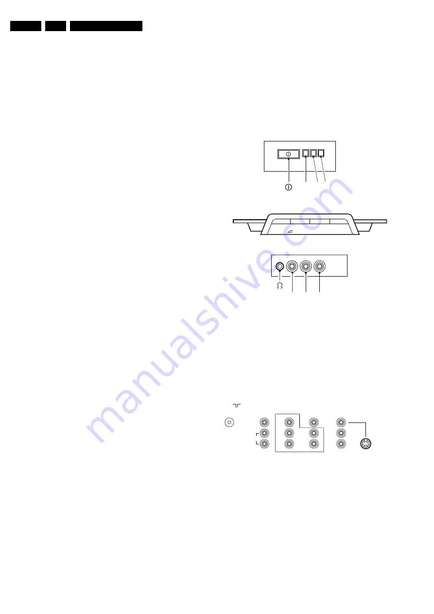
1.2.1
Top Control and Front / Side Connections
Figure 1-1 Top control and Front / Side connections
Audio / Video In
Ye - Video (CVBS) 1 V_pp / 75 ohm
jq
Wh - Audio - L
0.2 V_rms / 10 kohm
jq
Rd - Audio - R
0.2 V_rms / 10 kohm
jq
Bk - Headphone 8 - 600 Ohm / 4 mW
ot
1.2.2
Rear Connections
Figure 1-2 Rear connections
Aerial In
- F-type
Coax, 75 ohm
D
Monitor Out
Ye - Video (CVBS) 1 V_pp / 75 ohm
kq
Wh - Audio - L
0.5 V_rms / 1 kohm
kq
Rd - Audio - R
0.5 V_rms / 1 kohm
kq
YUV In
Bu - U
0.7 V_pp / 75 ohm
jq
Rd - V
0.7 V_pp / 75 ohm
jq
Gn - Y
0.7 V_pp / 75 ohm
jq
RED
LED
R AUDIO L VIDEO
E_14480_045.eps
170204
IR LIGHT SENSOR
(OPTIONAL)
TOP CONTROL
SIDE I/O
FRONT I/O
VOLUME
-
+
-
+
PROGRAM
P
VIDEO
L/Mono
R
Y
Pb
Pr
V
L
R
V
L
R
S-VIDEO
MONITOR
OUT
75 Ohm
AV1
IN
COMPONENT VIDEO INPUT
AV2
IN
E_14480_047.eps
110204
AUDIO
Summary of Contents for L04LAA
Page 36: ...Service Modes Error Codes and Fault Finding EN 36 L04L AA 5 E_06532_012 eps 130204 ...
Page 58: ...58 L04L AA 7 Circuit Diagrams and PWB Layouts Layout Mono Carrier Part 1 Bottom Side Part 1 ...
Page 93: ...Spare Parts List EN 93 L04L AA 10 10 Spare Parts List Not applicable ...
Page 94: ...Revision List EN 94 L04L AA 11 11 Revision List First release ...


