Directions for Use
EN 9
3.
C
OMPONENT
V
IDEO
(CVI) I
NPUT
C
ONNECTIONS
C
omponent V
ideo inputs pr
ovide
for the highest possible color
and pictur
e r
esolution in the play-
back of digital signal sour
ce materi-
al, such as with DVD players. The color differ
ence signals (Pb, Pr) and
the luminance (Y) signal ar
e con-
nected and r
eceived separately
,
which allows for impr
oved color
bandwidth information (not possible when using composite video or S- V
ideo connections).
1
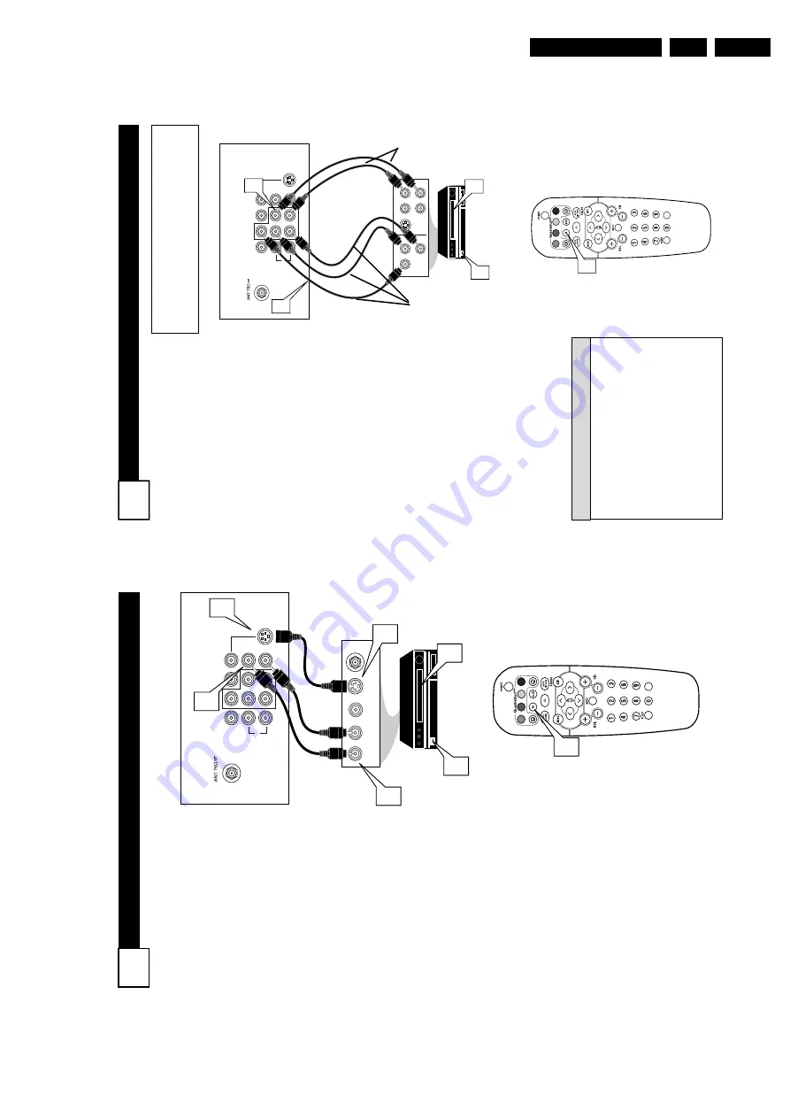
Connect the Component (Y
,
Pb, Pr)
V
ideo OUT
jacks from
the DVD player (or similar device) to the (Y
, Pb, Pr) in(put)
jack on the
TV
.
When using the
Component
V
ideo Inputs, it is
best not to connect a signal to the A
V
in V
ideo
Jack.
2
Connect the r
ed and white
AUDIO CABLES
to the
Audio
(left and right) output jacks on the rear of the accessory device to the
Audio (L
and R)
A
V1 in
Input Jacks on the
TV
.
3
T
urn the
TV
and the DVD (or
digital accessory device) ON.
4
Pr
ess the
A
V
button or
the
CH + or
CH – buttons
to
scroll the available channels until CVI appears in the upper left corner of the
TV
screen.
5
Insert a DVD disc into the DVD player and
pr
ess the
PLA
Y
䊳
button on the DVD
Player
.
The description for the component video
connectors may dif
fer depending on the
DVD player or accessory digital source
equipment used (for example,
Y
, Pb, Pr;
Y
,
B-Y
, R-Y
;
Y
, Cr
, Cb).
Although abbrevia-
tions and terms may vary
, the letters
b
and
r
stand for the blue and red color component
signal connectors, and
Y
indicates the lumi-
nance signal. Refer to your DVD or digital
accessory owner
’s
manual for definitions and
connection details.
H
ELPFUL
H
INT
VOL
L/Mono
Monitor out
VIDEO
S-VIDEO
AV
1
i
n
Y
Pb
Pr
A
V
2 in
AUDIO
R
COMPONENT
VIDEO INPUT
S-VIDEO
OUT
OUT
OUT
L
R
AUDIO
VIDEO
COMP
VIDEO
Y
Pb
Pr
2
1
3
5
4
Component
V
ideo Cables
(Green, Blue,
Red)
Audio
Cables
(Red &
White)
Accessory Device
Equipped with
Component V
ideo
Outputs
Back of
TV
The CVI connection will be dominate over the
A
V
1
in
V
ideo Input.
When a Component
V
ideo Device is
connected as described, it is best not to have a video
signal connected to the
A
V
1
in
V
ideo Input jack.
7
S-V
IDEO
(S-V
HS
) I
NPUT
C
ONNECTIONS
T
he S(uper)-V
ideo connection on
the r
ear of the TV
can pr
ovide
you with better pictur
e detail and
clarity for the playback of accessory
sour
ces such as DBS (digital br
oad-
cast satellite), DVD (digital video
discs), video games, and S-VHS VCR
(video cassette r
ecor
der) tapes than
the normal antenna pictur
e connec-
tions.
NOTE:
The accessory device must
have an S-VIDEO OUT(put) jack in
or
der for you to complete the connec-
tion on this page.
1
Connect one end of the S-
VIDEO CABLE
to the S-
VIDEO jack on the back of the
TV
.
Then connect one end the
AUDIO (red and white)
CABLES to the
A
V
1
in AUDIO
L
and R (left and right) jacks on
the rear of the
TV
.
2
Connect other
end of the S-
VIDEO CABLE
to the S-VHS
(S-V
ideo)
OUT
jack on the back
of the
VCR.
Then connect the
other ends of the
AUDIO (red
and white) CABLES to the
AUDIO (left and right) OUT
jacks on the rear of the
VCR.
3
T
urn the
VCR and the
TV
ON.
4
Pr
ess the
A
V
button or
the
CH + or
CH – buttons
on the
remote to scroll the channels
until SVHS appears in the upper
left corner of the
TV
screen.
5
Now your ready to place a pre-
recorded video tape in the
VCR
and
pr
ess the PLA
Y
䊳
button
.
VOL
L/Mono
Monitor out
VIDEO
S-VIDEO
A
V1 in
Y
Pb
Pr
A
V2 in
AUDIO
R
COMPONENT
VIDEO INPUT
AUDIO OUT
L
R
S-VIDEO
OUT
ANT/CABLE
OUT
VIDEO
OUT
1
2
1
2
3
5
4
VCR or External
Accessory Device
(with S-V
ideo
Output)
Audio Cables
(Red &
White)
S-V
ideo
Cable
Back of
TV
6
Summary of Contents for L04LAA
Page 36: ...Service Modes Error Codes and Fault Finding EN 36 L04L AA 5 E_06532_012 eps 130204 ...
Page 58: ...58 L04L AA 7 Circuit Diagrams and PWB Layouts Layout Mono Carrier Part 1 Bottom Side Part 1 ...
Page 93: ...Spare Parts List EN 93 L04L AA 10 10 Spare Parts List Not applicable ...
Page 94: ...Revision List EN 94 L04L AA 11 11 Revision List First release ...


