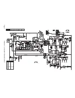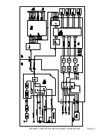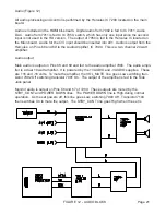
Main power supply (Figure 3)
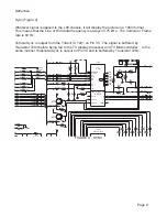
The Main Power supply provides the VBAT (141 volt), and Audio voltage supplies. This sup-
ply is switched Off during the Standby mode. During Standby the STBY_Con line is High
which turns Transistor 7573 On. This causes the opto-isolator 7513 to turn On hard. This
places a higher voltage on the control Pin of IC 7511 causing the IC to shut down. The
operating voltage from the Auxiliary supply keeps a small voltage on Pin 2 of 7511 to prevent
it from cycling On and Off. Output from Pin 11 of 7511 drives FET 7512 which drives
Transformer 5512. When Pin 2 of 5512 goes High, Transistor 7514 is switched On turning
7512 Off. This is to prevent 5512 from becoming saturated.
When the set is turned On, the STBY_Con line goes Low switching 7573 Off. The VBAT
supply is the reference voltage for regulation. Since this voltage is missing during startup, the
Shunt Regulator 7571 is turned Off. The voltage on Pin 6 of 7511 goes Low, which turns the
drive from the IC On. When the set is On during normal operation, the supply voltage on Pin
2 of the IC is supplied by Pin 2 of Transformer 5512. When the VBAT supply reaches the
correct voltage, Pin 3 of the Shunt Regulator 7571 reaches 2.5 volts switching it On. This
switches the opto-isolator On to provide a regulation feedback path.
Transistor 6551 provides a power on ramping of
the VBAT supply.
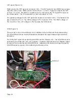
7512 drive test points.
Page 7
Summary of Contents for L05HD
Page 13: ...FIGURE 5 TV SIGNAL PROCESSOR Page 11 ...
Page 16: ...FIGURE 7 CONTROL Page 14 ...
Page 19: ...FIGURE 9 DETAILED VIDEO SIGNAL FLOW BLOCK Page 17 ...
Page 24: ...FIGURE 13 AUDIO OUTPUT Page 22 ...
Page 27: ...FIGURE 16 WIRING INTERCONNECT Page 25 ...
Page 28: ...Page 26 SERVICE POSITION ...
Page 32: ......


