background image

c. Qulckly move the soldering iron tip to the junction of the

component lead and the printed circuit foil, and hold it
there only until the solder flows onto and around both the
component lead and the foil.

CAUTION: 

Work quickly to avoid overheating the circuit

board printed foil.

d. Closely inspect the solder area and remove any excess

or splashed solder with a small wire-bristle brush.

IC Remove/Replacement

Some chassis circuit boards have slotted holes (oblong) through
which the IC leads are inserted and then bent flat against the
circuit foil. When holes are the slotted type, the following
technique should be used to remove and replace the IC. When
working with boards using the familiar round hole, use the
standard technique as outlined in parapraphs 5 and 6 above.

Removal

1.  Desolder and straighten each IC lead in one operation by

gently prying up on the lead with the soldering iron tip as the
solder melts.

2.  Draw away the melted solder with an anti-static suction-

type solder removal device (or with solder braid) before
removing the IC.

Replacement

1.  Carefully insert the replacement IC in the circuit boare.
2.  Carefully bend each IC lead against the circuit foil pad and

solder it.

3.  Clean the soldered areas with a small wire-bristle brush.

(It is not necessary to reapply acrylic coating to the areas).

"Small-Signal" Discrete Transistor
Removal/Replacement

1.  Remove the defective transistor by clipping its leads as

close as possible to the component body.

2.  Bend into a "U" shape the end of each of three leads

remaining on the circuit board.

3.  Bend into a "U" shape the replacement transistor leads.
4.  Connect the replacement transistor leads to the

corresponding leads extending from the circuit board and
crimp the "U" with long nose pliers to insure metal to metal
contact then solder each connection.

Power Output, Transistor Device
Removal/Replacement

1.  Heat and remove all solder from around the transistor leads.
2. Remove the heatsink mounting screw (if so equipped).
3.  Carefully remove the transistor from the heat sink of the

circuit board.

4.  Insert new transistor in the circuit board.
5. Solder each transistor lead, and clip off excess lead.
6.  Replace heatsink.

Diode Removal/Replacement

1.  Remove defective diode by clipping its leads as close as

possible to diode body.

2.  Bend the two remaining leads perpendicula y to the circuit

board.

3.  Observing diode polarity, wrap each lead of the new diode

around the corresponding lead on the circuit board.

4.  Securely crimp each connection and solder it.
5. Inspect (on the circuit board copper side) the solder joints of

the two "original" leads. If they are not shiny, reheat them
and if necessary, apply additional solder.

Fuse and Conventional Resistor
Removal/Replacement

1.  Clip each fuse or resistor lead at top of the circuit board

hollow stake.

2.  Securely crimp the leads of replacement component around

notch at stake top.

3.  Solder the connections.

CAUTION: 

Maintain original spacing between the replaced

component and adjacent components and the circuit board
to prevent excessive component temperatures.

Circuit Board Foil Repair

Excessive heat applied to the copper foil of any printed circuit
board will weaken the adhesive that bonds the foil to the circuit
board causing the foil to separate from or "lift-off" the board.
The following guidelines and procedures should be followed
whenever this condition is encountered.

At IC Connections

To repair a defective copper pattern at IC connections use the
following procedure to install a jumper wire on the copper
pattern side of the circuit board. (Use this technique only on IC
connections).

1.  Carefully remove the damaged copper pattern with a sharp

knife. (Remove only as much copper as absolutely
necessary).

2.  carefully scratch away the solder resist and acrylic coating

(if used) from the end of the remaining copper pattern.

3.  Bend a small "U" in one end of a small gauge jumper wire and

carefully crimp it around the IC pin. Solder the IC connection.

4.  Route the jumper wire along the path of the out-away

copper pattern and let it overlap the previously scraped end
of the good copper pattern. Solder the overlapped area and
clip off any excess jumper wire.

At Other Connections

Use the following technique to repair the defective copper
pattern at connections other than IC Pins. This technique
involoves the installation of a jumper wire on the component
side of the circuit board.

1.  Remove the defective copper pattern with a sharp knife.

Remove at least 1/4 inch of copper, to ensure that a
hazardous condition will not exist if the jumper wire opens.

2.  Trace along the copper pattern from both sides of the

pattern break and locate the nearest component that is
directly connected to the affected copper pattern.

3.  Connect insulated 20-gauge jumper wire from the lead of

the nearest component on one side of the pattern break to
the lead of the nearest component on the other side.
Carefully crimp and solder the connections.

CAUTION: 

Be sure the insulated jumper wire is dressed so

the it does not touch components or sharp edges.

Summary of Contents for LC1.15E

Page 1: ... otherwise without the prior permission of Philips Colour Television Chassis LC1 15E AA Contents Page Safety Precautions 2 Servicing Precautions 3 Description of Controls 5 Troubleshooting 8 Wiring Diagram 9 Block Diagram 10 Main Board for LC151x01 A3 LCD Panel 11 Main Board PWB for LC151x01 A3 LCD Panel 12 13 Control and Tuner Panel PWB 14 Main Board for LC151x01 C3P1 LCD Panel 15 Main Board PWB ...

Page 2: ...rform an AC leakage current check on the exposed metallic parts of the cabinet such as antennas terminals etc to be sure the set is safe to operate without damage of electrical shock Leakage Current Cold Check Antenna Cold Check With the instrument AC plug removed from AC source connect an electrical jumper across the two AC plug prongs Place the AC switch in the on positioin connect one lead of o...

Page 3: ...e integrated circuits and some fieldeffect transistors and semicounductor chip components The following techniques should be used to help reduce the incidence of component damage caused by static by static electricity 1 Immediately before handling any semiconductor component or semiconductor equipped assembly drain off any electostatic charge on your body by touching a known earth ground Alternati...

Page 4: ...e corresponding lead on the circuit board 4 Securely crimp each connection and solder it 5 Inspect on the circuit board copper side the solder joints of the two original leads If they are not shiny reheat them and if necessary apply additional solder Fuse and Conventional Resistor Removal Replacement 1 Clip each fuse or resistor lead at top of the circuit board hollow stake 2 Securely crimp the le...

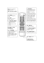
Page 5: ...ansmission select mono reception Sound output selection in AV mode In AV mode you can select the output sound for the left and right loudspeakers Press the X key repeatedly to select L R the audio signal from the audio L input is sent to the left loudspeaker the audio signal from the audio R input to the right loudspeaker L L the audio signal from the audio L input is sent to the left and right lo...

Page 6: ...it keys To select a TV channel 0 Previous programme To display the previously selected TV channel LIST Programme list To display the programme list b Teletext on off Teletext functions hUfgcek D Sleeptimer With this key you can set a time period after which the TV should switch itself to standby Press the key repeatedly to select the number of minutes The counter runs from B 0 10 20 30 to 240 minu...

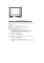
Page 7: ...ed for about 10 seconds All the menus are being displayed automatically one after the other To stop Auto demonstration press any key on the front panel VOL Press or to select a menu item Press or to adjust the volume Press or to adjust the menu settings CH PR Press or to browse through the TV channels which are not skipped Press or to select a menu item To switch the TV on from standby B Switches ...

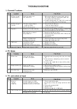
Page 8: ...air the IC801 802 SI4925 P502 and Pin 21 connector 1 Check and fix P502 connector being slipped out 2 Check and fix the components at P502 LCD module and at main board 3 Check Pin21 Cracked components and 1 Check and repair tuner board and main board soldering at tuner board 2 Solder Q403 Q402 and C153 4 Dark screen 1 Defective LCD lamp 1 Replace the inverter 2 Defective inverter 2 Replace the LCD...

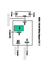
Page 9: ... Diagram 15 1 To Lamp Tuner To Panel P502 9965 000 20403 A3 Panel 9965 000 20404 C3 Panel P801 P401 P601 To Speaker P602 6631V25016G 3P 6631V25016P 4P To Lamp To Control PWB 9965 000 20401 A3 Panel 9965 000 20402 C3 Panel ...

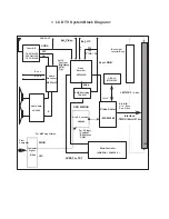
Page 10: ... D Sub R G B H V D R G B H V Sync Den Clock From Computer OSD IC MC141585 CVBS Audio Amp LA4282 R Ext R SIF For MNT Application LM151X3 8 bits 1H 1V A to D Converter AD9884 For PC Input Contrast Brightness Color Ext_Video Ext_Y C OSD B R G B Scart RGB For TV Contrast Brightness Color Tint CVBS For TXT AM Interface TMDS 8bits 21 pin RGB Switching TDA8601 Y Cb Cr RGB in Back Light Inverter Assy CVBS...

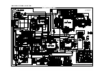
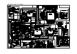
Page 11: ...Service Sheet of MF 004A P N 3854VA0077A S DATE 2000 10 02 Main Board for LC151X01 A3 LCD Panel ...

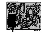
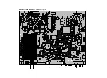
Page 12: ...Main Board for LC151X01 A3 LCD Panel Top Side ...

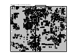
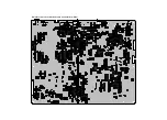
Page 13: ...Main Board for LC151X01 A3 LCD Panel Bottom Side ...

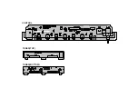
Page 14: ...CONTROL TUNER TOP TUNER BOTTOM ...

Page 15: ...Main Board for LC151X01 C3P1 LCD Panel ...

Page 16: ...Main Board for LC151X01 C3P1 LCD Panel Top Side ...

Page 17: ...Main Board for LC151X01 C3P1 LCD Panel Bottom Side ...

Page 18: ...CONTROL TUNER TOP TUNER BOTTOM ...

Page 19: ... TV 3 Lean the set 45 backward Adjustment is easy 4 Set the PC mode menu as below 3 3 White Adjustment 1 Approve the signal of 64 tones of XGA 1024 768 2 Select all the gain of R B and G with using ADJ of remote control 3 After making 62 tones 63 tones and 64 tones not distinguished with using each signal of R G and B finish adjusting at the moment when the signal 62 63 and 64 is distinguished ADJ...

Page 20: ...49 400 49 2 POS 34 13 SVGA 56 1024 800 224 72 POS 128 24 35 156 36 0 625 600 25 2 POS 22 1 SVGA 60 1056 800 256 128 POS 88 40 37 879 40 0 628 600 28 4 POS 23 1 SVGA 72 1040 800 240 120 POS 64 56 48 077 50 0 666 600 66 6 POS 23 37 Mode H_Total H_Display H_Blanking H_Sync H Polarity H_Bp H_Fp H Freq KHz Clk MHz V_Total V_Display V_Blanking V_Sync V Polarity V_Bp V_Fp SVGA 75 1056 800 256 80 POS 160 ...

Page 21: ...EXPLODED VIEW 112 540 500 550 521 541 120 530 310 400 401 410 ...

Page 22: ...C1001 9965 000 16429 100µF 10V C1002 9965 000 16430 0 01µF 80 50V C101 9965 000 16431 10µF 16V C115 9965 000 16432 100µF 16V C117 9965 000 16432 100µF 16V C120 9965 000 16431 10µF 16V C121 9965 000 16433 47µF 16V C125 9965 000 16434 10µF 50V C127 9965 000 16432 100µF 16V C131 9965 000 16432 100µF 16V C133 9965 000 16435 4 7µF 50V C133 9965 000 16441 22µF 16V C134 9965 000 16433 47µF 16V C137 9965 ...

Page 23: ...3216 4S600 LA516 9965 000 16489 Filter 3216 4S600 LA517 9965 000 16489 Filter 3216 4S600 LA518 9965 000 16489 Filter 3216 4S600 LA519 9965 000 16489 Filter 3216 4S600 LA520 9965 000 16489 Filter 3216 4S600 LA521 9965 000 16489 Filter 3216 4S600 LA522 9965 000 16489 Filter 3216 4S600 LA523 9965 000 16489 Filter 3216 4S600 LA524 9965 000 16489 Filter 3216 4S600 LA525 9965 000 16489 Filter 3216 4S600...

Page 24: ... panel IC805 and IC807 are changed from SI9936DY 9965 000 16476 into SI4808DY 9965 000 16573 to improve the function 4 The LCD panel LC151X01 A3 has been changed into the LC151X01 C3P1 This change is introduced in sets with serial number AG990230 and higher At the same time also the following parts are changed LCD panel LC151X01 A3 9965 000 16410 into LC151X01 C3P1 9965 000 16743 Main board from 9...

Reviews: