Mechanical Instructions
EN 12
LC4.41A AA
4.
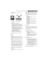
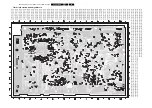
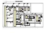
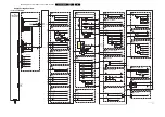
Figure 4-13 Plasma panel removal (3/3)
To remove the Plasma-panel, carry out the following steps:
1.
Remove the rear cover from the set.
2.
Cautiously
unplug the LVDS connector [1] from the SSB
panel (see Figure “LVDS connector”).
Be careful
, as this is a very fragile connector/cable!
3.
Unplug the other connectors [2] from the SSB panel.
4.
Unplug the connectors 1M03 and 1M46 [3] from the Power
Supply board.
5.
Unplug the power connector CN1305 [4] from the Power
Supply board.
6.
Unplug the connectors [5] from the Audio Panel.
7.
Loosen the fixation screw [6] from the earth tab on the
display.
8.
Loosen the fixation screw [7] just above the SSB panel.
9.
Loosen screw [8] with the cable clamp.
10. Release all disconnected cables from the (mostly plastic)
guidances on the frame.
11. Loosen screws [9].
12. Lift the metal frame [10] (together with the SSB) from the
plasma panel.
13.
Cautiously
unplug the LVDS connector [11] from the Logic
Board of the Plasma panel (see Figure “Logic Board”).
Be careful
, as this is a very fragile connector/cable!
14. Remove the bronze spacer [12] from the stud on the
plasma panel.
15. Now you can lift the Plasma display from its plastic frame.
16. If the plastic frame is damaged, replace it by a new frame,
after removing the loudspeakers, the Side I/O panel, the
Side Control panel, and the LED panel.
4.4
Set Re-assembly
To re-assemble the whole set, execute all processes in reverse
order.
Notes:
•
While re-assembling, make sure that all cables are placed
and connected in their original positions. See Figure “Cable
dressing”.
Be careful with the fragile LVDS cable.
G_16240_022.eps
160206
12
11


