Circuit Descriptions, Abbreviation List, and IC Data Sheets
EN 74
LC4.41A AA
9.
9.
Circuit Descriptions, Abbreviation List, and IC Data Sheets
Index of this chapter:
9.1 Introduction
9.2 Block Diagram
9.3 Power Supply Unit
9.4 Abbreviation List
9.5 IC Data Sheets
9.1
Introduction
The LC4.41 chassis is a global chassis for the year 2006. It is
the successor of the LC4.3 chassis and covers screen sizes of
42 and 50 inch in the AP region (in 16:9 ratio). The styling which
is used is called ME5FL. Pixel Plus ensures additional picture
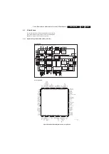
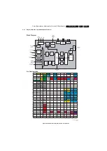
quality improvement. The block diagram below (Figure “Block
diagram Pixel Plus Architecture”) shows the Pixel Plus
architecture.
The architecture consists of a TV and Scaler panel, I/O panel,
Side I/O and Local Keyboard panel and Power Supply panel.
The functions for video/audio processing, microprocessor (P),
and CC/Teletext (TXT) decoder are all combined in one IC
(TDA150xx, item 7217), the so-called third generation Ultimate
One Chip (UOC-III) or “Hercules”. This chip has the following
features:
•
Control, small signal, mono/stereo, and extensive Audio/
Video switching in one IC.
•
Upgrade with digital sound & video processing.
•
Alignment free IF, including SECAM-L/L1 and AM.
•
FM sound 4.5/5.5/6.0/6.5, no traps/bandpass filters.
•
Full multi-standard colour decoder.
•
One Xtal reference for all functions (microprocessor, RCP,
TXT/CC, RDS, colour decoder, and stereo sound
processor).
9.2
Block Diagram
Figure 9-1 Block Diagram Pixel Plus Architecture
The function is basically the same as in the LC4.3A AA, with the
following differences:
•
The model range only contains models with Pixel Plus;
•
Pixel Plus is performed by a new IC, called Pacific 3.
The Pacific 3 IC provides additional sharpening, and contrast
and colour enhancements to the picture.
For more information, please refer to manual LC4.3A AA,
12NC 3122 785 15290.
9.3
Power Supply Unit
There are two types of Power Supply Units used in the various
models of this chassis. Both Supply Units come with the PDP
Panel and are a “Black Box” for Service. For Block Diagrams,
Circuit Diagrams, PWB Layouts and Alignments, please refer
to the PDP Repair Manual (see reference on the front page).
TUNER
IF
CVBS
CVBS,U,V
A/D
AD9945
COLUM-
BUS
SCALER
LV
DSRx
SDRAM
HDMI
NVM FLASH DDR
LCD
PANEL
601 INTERF.
601 INTERF.
D
V
I TMDS
601 INTERFACE
Y
C
HERCULES
INTERNAL LIP SYNC CKT
SM5301
DVI-I
HDMI
DMMI
HP
NVM
AUDIO
AMPLIFIER
ComPair
SCART/
CINCH
I/O
TO
AUDIO
AMP
P
A
CIFIC 3
LV
DSRx
G_16210_093.eps
200106


