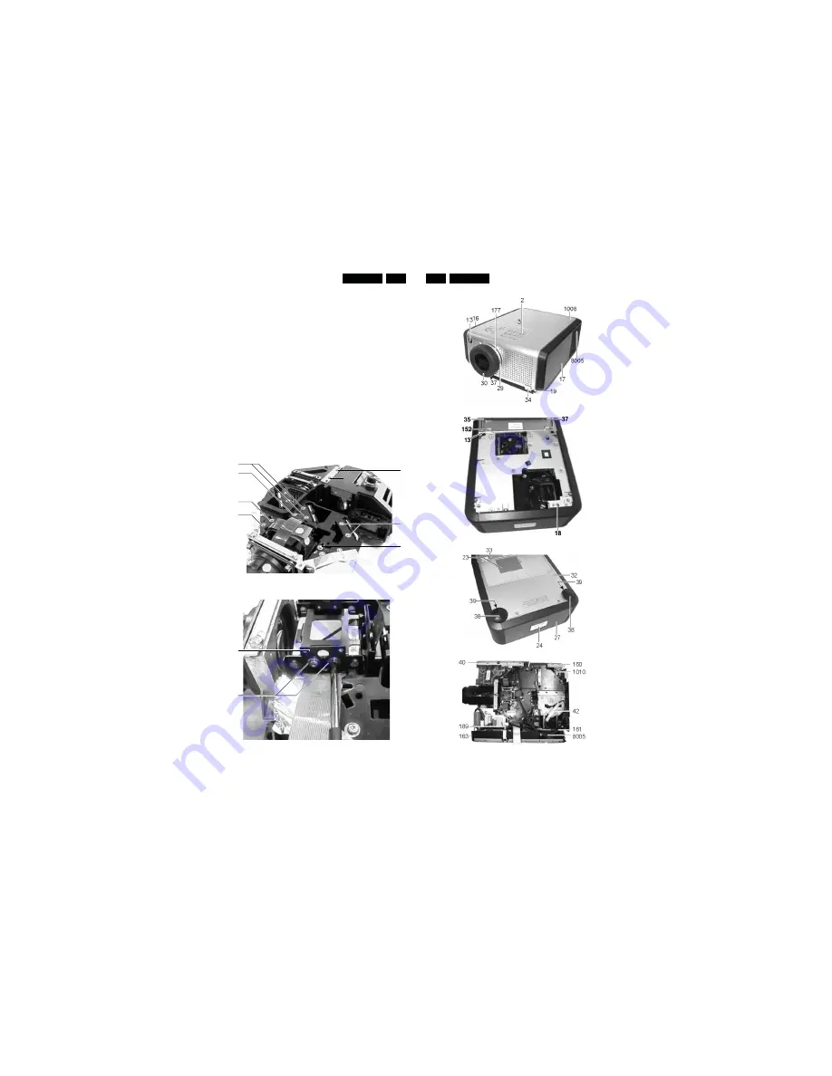
All the mirrors can be aligned, however only the mirrors
mentioned below should be aligned. To place a mirror in it’s
nominal position, put a 2mm wide spacer between the mirror
and the lighthouse, and then fix the mirror.
8.1
Integrator 1
Put on a white picture. If dark bars are visible on the edges,
then integrator 1 has to be aligned. Unscrew the 2 screws (A)
on top of integrator 1, and the integrator can be moved
left-right. Align for minimal dark bars, and if possible align for
middle position between dark edges. If dark edges are visible
in the top or bottom, adding or removing small filling plates
below the bracket fixing the integrator can align this.
8.2
Mirror B
Put on a green picture. If dark bands are visible on the sides,
loosen the two screws (B) fixing the mirror on top, and move
the mirror till the dark bands are gone.
8.3
Mirror C
Put on a red picture. If dark bands are visible on the sides,
loosen the two screws (C) fixing the mirror on top, and move
the mirror till the dark bands are gone.
8.4
Mirror D1
Put on a blue picture. If dark bands are visible on the sides,
loosen the two screws (D) fixing the mirror on top, and move
the mirror till the dark bands are gone.
8.5
Lens 3 green assy (polarizer green)
Put on a black picture. Loosen the screw (E) on top.
Move the screw for minimal green in the picture.
8.6
Lens 3 red assy (polarizer red)
Put on a black picture. Loosen the screw (F) on top.
Move the screw for minimal red in the picture.
8.7
Lens 6 blue assy (polarizer blue)
Put on a black picture. Loosen the screw (G) on top.
Move the screw for minimal blue in the picture.
8.8
Convergence alignment
Remove the drive board. If the set is now switched on the
picture will be fully white. Any convergence error will show up
as a coloured band at one side of the picture.
The convergence should be aligned in such a way that the
coloured bands are minimal.
Please note the projector will only work for a few minutes in
this position. If the projector switches off, remove the mains,
plug it back in, and the projector will work again. Putting the
projector is service mode will stop it from switching off.
To align the convergence loosen the two torkx screws (H) at
the top of the LCD-holding plate so, that you can move the
holding plate with the LCD freely, but not easily. Now grab the
top of the holding plate (J) with the fingers of 2 hands. Move
the plate with the LCD till the convergence is optimal (no
coloured band on the side). This is easiest by first getting the
picture straight, then moving the picture left right and then
moving the picture up/down.
Always align convergence of red and blue with respect to
green.
LC4043
LC4043
8.
Alignments
8-1
9-1
9.
Parts lists - Mechanical parts
PCS 92 693 GB
PCS 92 694 GB
D
A
G
C
F
E
B
Fig. 8.1
J
H
Fig. 8.2
2
Light guide knobs
4822 380 10248
3
Knob set keyboard
4822 410 12096
13
Spring for foot knob
4822 492 11695
16
Cover connector side
3122 438 10890
17
Cover fan side
4822 442 01588
19
Adjustable foot
4822 462 11123
29
Zoom ring
3122 434 20890
30
Focus ring
3122 434 20720
34
Foot knob assy
4822 410 12095
37
Clip for foot
4822 401 11779
177
Zoom ring screw
4822 502 14624
1008
Top cover assy
4822 442 01815
8005
Fan for lamp (+ cable)
3122 431 01280
13
Spring for foot knob
4822 492 11695
18
Switch, mains
4822 276 14034
35
Foot rack
4822 402 11188
37
Clip for foot
4822 401 11779
152
Ring fixing foot
4822 530 70124
23
Dust filter
4822 480 10229
24
Logo Hopper
3122 438 10910
27
Rear cover
4822 426 10744
32
Door assy
3122 438 10870
33
Bottom cover
4822 442 01589
38
Rear foot
4822 462 11124
39
Foot spring rear
4822 492 11696
40
Mains input socket
4822 264 10386
42
Thermal switch
2622 799 40275
160
Clamp for speaker
4822 401 11781
161
Clamp for lamp fan
4822 401 11782
163
Dist. piece lamp supply
4822 404 10967
189
Dist. piece powr. supply
4822 404 10968
1010
Loudspeaker 16R 2W
4822 240 10333
8005
Fan for lamp (+ cable)
3122 431 01280


