Mechanical Instructions
4.
4.3
Assy/Panel Removal MG8 Styling
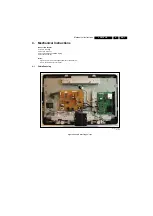
Pictures are taken from 32” set.
4.3.1
Rear Cover
Warning:
Disconnect the mains power cord before you remove
the rear cover.
You can remove the backcover without removing the stand.
4.3.2
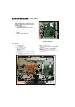
Speakers
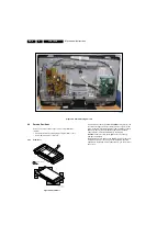
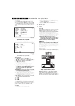
Refer to next figure for details.
1.
Unplug the connectors [1].
2.
Remove the screws [2] and lift the speaker from the back
cover.
Figure 4-4 Speakers
4.3.3
IR & LED Panel
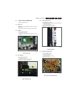
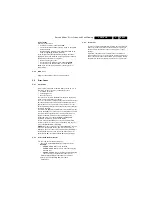
Refer to next figure for details.
1.
Unplug connectors [1].
2.
Release the clips and take the panel out.
When defective, replace the whole unit.
Figure 4-5 IR & LED Board
4.3.4
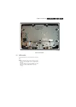
Keyboard Control Panel
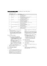
Refer to next figure for details.
1.
Unplug the key board connector from the IR & LED board.
2.
Remove the screws [1].
3.
Lift the unit and take it out of the set.
When defective, replace the whole unit.
Figure 4-6 Key Board
4.3.5
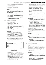
Main Power Supply Panel 32"
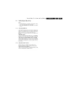
Refer to next figure for details.
1.
Unplug connectors [1].
2.
Remove the fixation screws [2].
3.
Take the board out.
When defective, replace the whole unit.
Figure 4-7 Main Power Supply Panel 32"
I_17911_001.ep
s
3
0060
8
2
2
1
(
2x
)
I_17911_002.ep
s
3
0060
8
1
1
I_17911_00
3
.ep
s
3
0060
8
1
1
2
2
2
2
2
2
1
1
1
(
2x
)
I_1
8
170_050.ep
s
3
1070
8


