background image

Light System Manager    Product Guide

10

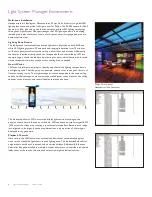
About Light System Composer Software

Light System Composer is a full-featured software package containing the following 

modules:

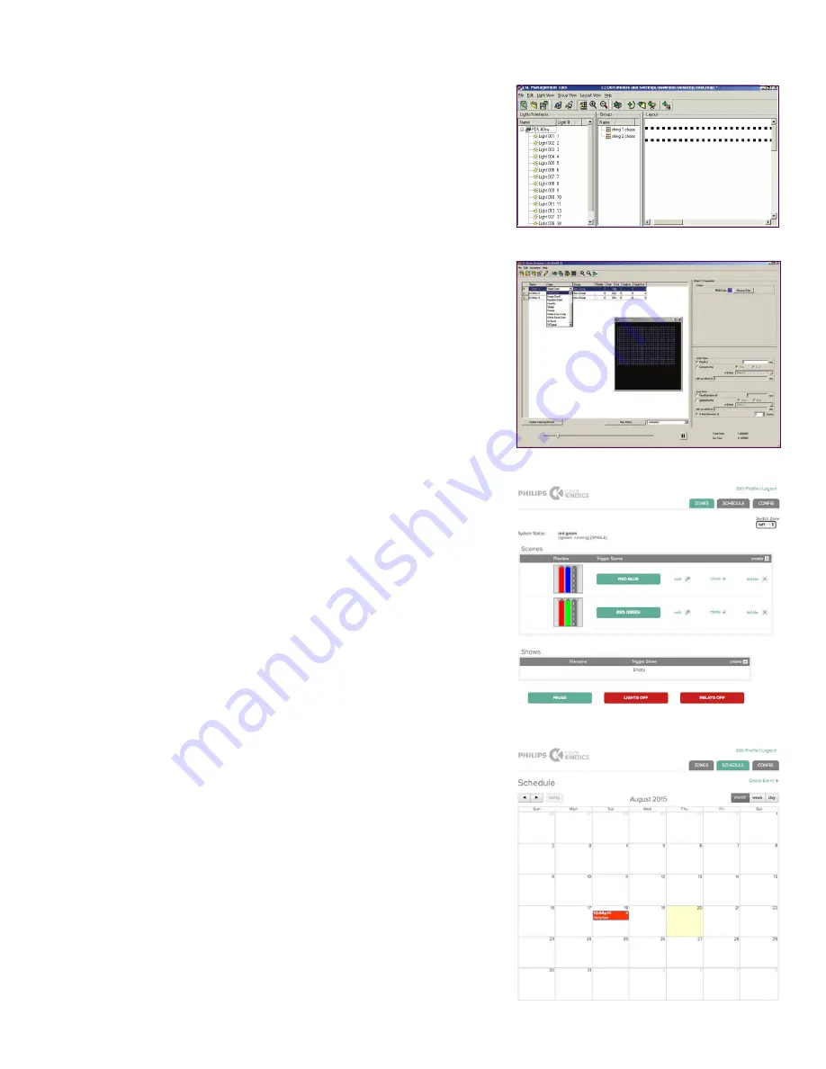
Management Tool

 — 

When connected to a lighting network, the Management Tool 

module automatically discovers all lighting system components, allowing you to create 

a map of the installation. The map identifies all hardware so that the LSE controller can 

send accurate light output instructions. Additionally, Management Tool allows you to 

create groups of fixtures that can have colors or effects applied to them using Show 

Designer or the Web Interface.  

Show Designer

 —

 The Show Designer module enables you to author and refine 

dynamic light shows using eight fixed color and chasing color effects, two animated 

image effects, and two geometric effects. You can apply pre-defined effects to groups of 

fixtures, and then modify those effects by modifying their parameters. Show Designer 

also allows you to simulate your show via the Live Play simulation feature, which 

displays the light shows on the fixtures in your installation.

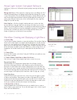
Workflow: Creating and Displaying a Light Show

1. Create a Map

The first step in creating a light show is to map the installation. The map links all lighting 

fixtures and interfaces (power / data supplies and Data Enablers) to the LSE controller, 

and acts as a virtual representation of the installation. The Management Tool module 

enables you to automatically discover all lighting system components and build the map. 

When new fixtures are added to an existing installation, or when working off site, the 

Management Tool module also allows you to manually build a fully functional virtual 

map.

2. Create a Zone 

Access the Web Interface, and click the Config tab. Click Zones, and upload your map 

file to create a new zone.

3. Create a Dynamic Light Show or Static Color Scene

After the zone is created, create a dynamic light show or static color scene. 

Dynamic Light Show

Use Show Designer to create dynamic lighting effects. Show Designer lets you 

add effects to each group of fixtures in the installation and then modify the effect 

parameters to create unique results. Use the Live Play feature to test and refine your 

show. Once your show is created, use the built-in Web Interface to upload your show 

file and any related image assets. Each animation effect requires a zip file containing the 

animation images. Each image scroll effect requires an image file (.png, .jpg, or .bmp)

Static Color Scene

Use the Web Interface to create static color scenes. Colors can be applied to groups 

of lights in your installation. These groups are created in Management Tool, and are 

assigned to point-and-click areas through the group map editor, which is located in the 

Configuration tab of the Web Interface. You can use the scene editor to select colors 

live on your installation while the selected scene is actively playing. 

4. Schedule Show or Scene

Using the Schedules tab of the Web Interface, you can schedule shows or scenes to 

play at a fixed or astronomical time. You can manually trigger a show or scene using the 

Zones tab of the Web Interface.

Management Tool

Show Designer

Show Schedule Calendar

Static Color Scene

Summary of Contents for Light System Manager

Page 1: ...Light System Manager Author configure and control intricate LED light shows in multiple zones ...

Page 2: ...olor scenes using an online web interface The web interface supports multiple online users with activity logging for each user account Simplified control access Designed for use with LSM Ethernet Controller Keypad is a wall mounted triggering device that controls light shows and fixture brightness at the touch of a button LSM supports up to 10 keypads within a single lighting installation Dual con...

Page 3: ...e CN Tower project Installed with standard Ethernet cabling and network hardware LSM manages the 1 300 high performance lighting fixtures mounted within the Tower s elevator shafts and antenna tower What s in a Light System Manager Light Show A light show is a set of digital instructions orchestrating how and when your lighting installation displays effects The CN Tower lighting design team create...

Page 4: ...nal maps to identify and control the lighting components in each lighting zone The lobby map for example contains four rectangular clusters of fixtures varying in size The large rectangular area corresponds to the main ceiling and the smaller rectangular areas match the wall adjacent to the elevator the ceiling adjacent to the elevator and the wall behind the reception desk 0 seconds 60 120 180 24...

Page 5: ...LSM s scalable Ethernet based design proved critical to the success of the complex project which features intricate and varied designs for the thousands of LED nodes and fixtures within the hotel Light System Manager s compatibility with commonly used network components allowed for reliable and seamless installation Light System Manager controls eight separate lighting zones including the Hard Roc...

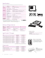
Page 6: ...er Ethernet switches or PoE injectors when installing a lighting system containing one or more Ethernet Controller Keypads Included in the Box 9 5 in 241 mm 10 2 in 260 mm 11 8 in 301 mm 11 9 in 303 mm 10 6 in 270 mm 2 3 in 60 mm 1 6 in 41 mm System Requirements Specification PC Mac Software Operating System Windows 8 Windows 7 Mac OS X 10 6 or greater Hardware Memory 256 MB RAM 256 MB RAM Disk sp...

Page 7: ...istance Ethernet Controller Keypads are Power over Ethernet PoE devices Use PoE compatible Ethernet switches if Ethernet Controller Keypads are installed on the network Alternatively if using non PoE switches install PoE injectors from Philips Color Kinetics inline between each keypad and switch Dedicated Local Area Network To achieve optimal display and network connectivity performance the lighti...

Page 8: ...imum individual cable runs to 328 ft 100 m For larger installations adding Fiber optic data cabling and hardware to your lighting network extends the maximum cable run distance 4 As part of the lighting design plan where possible make use of a repeated layout that specifies the preferred orientation of each fixture For example if using iColor Tile MX fixtures install each fixture in a uniform mann...

Page 9: ...ighting network After connecting the personal computer verify that the computer can connect to the LSE Note that following light show programming and configuration you can disconnect and remove the personal computer from the network Refer to the Light System Manager User Guide for additional details as needed The Light System Manager User Guide is available online at www colorkinetics com ls contr...

Page 10: ...ld the map When new fixtures are added to an existing installation or when working off site the Management Tool module also allows you to manually build a fully functional virtual map 2 Create a Zone Access the Web Interface and click the Config tab Click Zones and upload your map file to create a new zone 3 Create a Dynamic Light Show or Static Color Scene After the zone is created create a dynam...

Page 11: ...jump cut from one color to the next in random order Sparkle When applied to a group of fixtures flashes of light appears on several fixtures in the group in random order Streak When applied to a group of fixtures a pulse of color races from fixture to fixture XY Burst Produces multiple expanding concentric circles of color XY Spiral Produces a color changing wheel revolving around a center point W...

Page 12: ... the Color Kinetics logo ColorBlast ColorBlaze ColorBurst ColorGraze ColorPlay ColorReach iW Reach eW Reach DIMand EssentialWhite eW iColor iColor Cove IntelliWhite iW iPlayer Optibin and Powercore are either registered trademarks or trademarks of Philips Solid State Lighting Solutions Inc in the United States and or other countries All other brand or product names are trademarks or registered tra...

Reviews: