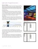
Light System Manager Product Guide
7
Light System
Manager
100–240 VAC
Ethernet
Controller
Keypads
(optional)
Ethernet Switch
ColorBlast Powercore
Fixtures
Data Enabler
Pro
PC or
Mac
CAT 5e Cable
CAT 5e Cable
Internet
Lighting Network
Configuration Overview
Light System Manager allows your lighting installation to display of a variety of light show
designs and choreographed moving images. LSM comprises Light System Engine, a computer
(for initial setup and programming), one or more Ethernet Controller Keypads (optional),
network hardware, and lighting components.
Ethernet Layout
Light System Engine hardware communicates with the interfaces in the lighting installation
(power / data supplies and Data Enabler Pro devices) via KiNET Ethernet, the network
protocol engineered by Philips Color Kinetics for high-performance lighting system control.
LSE offers full compatibility with all conventional Ethernet hardware, accommodating
network trees up to three switches deep between the LSE and the farthest KiNET interface.
Ethernet limits the maximum cable run to 328 ft (100 m). Adding Ethernet optical data
cabling and hardware to your layout extends the maximum cable run distance.
Ethernet Controller Keypads are Power over Ethernet (PoE) devices. Use PoE-compatible
Ethernet switches if Ethernet Controller Keypads are installed on the network.
Alternatively, if using non-PoE switches, install PoE injectors from Philips Color Kinetics
inline between each keypad and switch.
Dedicated Local Area Network
To achieve optimal display and network connectivity performance, the lighting network port
(
) of the LSE and all lighting components must be installed on a dedicated Local Area
Network. Light System Engine hardware delivers thousands of packets of light output data
per second to your lighting installation, requiring uninterrupted data throughput.
You can use the Internet network port (
) to connect to an existing building network,
and maintain Internet connectivity.
Automatic Interface Discovery and Creating Maps
Light System Engine references a map file when communicating with the lighting components
in the network. The map allows the LSE to identify every fixture and interface in the
installation as a separate device and route data accordingly. For your convenience, the
Management Tool module in Light System Composer automatically discovers all connected
Ethernet interfaces and fixtures, including their IP addresses and device names.
E
For optical device Ethernet network
specifications, refer to your optical device user
documentation.


