background image

LRC2410 Installation Instructions, Part No. CDCS000314 Rev. A 7/11

Page 1

LRC2410

8X20A Relay Control Panel

BACnet MS/TP Enabled

INSTALLATION INSTRUCTIONS

    WARNING

To reduce the risk of death, injury or property damage from fire, electric shock, cuts, 

abrasions, falling parts, and other hazards:

• 

Service of the equipment must be performed by qualified service personnel.

• 

Installation and maintenance must be performed by a person familiar with the construction 

and operation of this product and any hazards involved. All applicable codes and ordinances 

must be followed.

• 

Read this document before installing, servicing, or maintaining this equipment. These 

instructions do not cover all installation, service, and maintenance situations. If your situation 

is not covered, or if you do not understand these instructions or additional information is 

required, contact 

Philips Lighting Controls.

    WARNING

Before installing, servicing, or maintaining this equipment, follow these general precautions.

To reduce the risk of electrocution:

• 

Make sure the equipment is properly grounded.

• 

Always de-energize any equipment before connecting to, disconnecting from, or 

servicing the equipment.

To reduce the risk of fire:

• 

Use supply conductors with a minimum installation temperature rating as specified.

To reduce the risk of personal injury from cuts, abrasions:

• 

Wear gloves to prevent cuts or abrasions from sharp edges when removing from 

carton, handling and maintaining this equipment. 

• 

Do not install a damaged equipment.

IMPORTANT SAFETY INSTRUCTIONS

READ AND FOLLOW ALL SAFETY INSTRUCTIONS!

SAVE THESE INSTRUCTIONS AND DELIVER TO OWNER AFTER INSTALLATION 

!

!

Summary of Contents for LRC2410

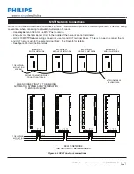
Page 1: ...nce situations If your situation is not covered or if you do not understand these instructions or additional information is required contact Philips Lighting Controls WARNING Before installing servicing or maintaining this equipment follow these general precautions To reduce the risk of electrocution Make sure the equipment is properly grounded Always de energize any equipment before connecting to...

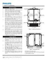
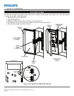
Page 2: ...r all warnings and proper safety procedures can cause severe injury or death and or damage to the equipment Figure 1 Conduit and Cable Entry Figure 2 Cabinet Dimensions 1 Mount the cabinet using the four holes provided in the back of the enclosure Refer to Figure 2 for dimensions 2 Choose the desired location for line voltage and low voltage conductor entry in the cabinet DO NOT install conduit wh...

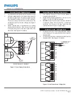
Page 3: ...the LRC2410 2 Relay terminal block specification 1 10 12 14 AWG or 2 12 14 AWG maximum 3 DO NOT connect 2 pole circuits or loads to LRC2410 single pole relays this will void the equipment warranty For 2 pole or 30 Amp loads use the optional LRC2410 2 pole 30 Amp relays Figure 4 Load Connections 8 Single Pole NEUTRAL CONTROLLER POWER SUPPLY TRANSFORMER PILOT LIGHT TRANSFORMER N C FRONT EDGE OF CABI...

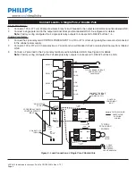
Page 4: ...ker to the 2 pole relay terminal positions labeled LINE 3 Connect a 2 pole load to the 2 pole relay terminal positions labeled LOAD See Figure 5 for details Note Factory wiring configures the 2 double pole relay outputs to correspond to RELAY buttons 5 and 6 Figure 5 Load Connections 4 Single Pole 2 Double Pole LOAD LOAD COIL OUTPUTS 7 AND 8 COIL OUTPUTS 5 AND 6 RELAY 4 LINE BLUE RED LOAD RELAY 1 ...

Page 5: ...s labeled LOAD See Figure 6 for details Note Factory wiring configures the 4 double pole relay outputs to correspond to RELAY buttons 1 4 COIL OUTPUTS 3 AND 4 WHITE RED 3 4 2 1 BLUE RED LINE LOAD LINE LINE COIL LINE BLUE LINE LOAD LOAD LOAD TYPICAL 2 POLE LOAD WIRING LINE LINE LOAD LOAD LINE LINE LOAD LOAD 2 POLE LOAD COIL NEUTRAL WHITE COIL LINE RED COIL 3 4 NEUTRAL CONTROL POWER 120 277 NEUTRAL ...

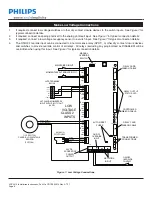
Page 6: ...DER LATCHING MOMENTARY INPUT WITH PILOT LIGHT LVPS LOW VOLTAGE CLASS 2 INPUTS RELAY OUTPUT STATUS LED 1 8 ON OFF OVERRIDE INPUT ON OFF OVERRIDE CONTACT OCC SWITCH CLASSIC LOW VOLTAGE SENSOR TYPICAL ANALOG PHOTOCELL Make Low Voltage Connections 1 If required connect low voltage switches or other dry contact closure devices to the switch inputs See Figure 7 for typical connection details 2 If requir...

Page 7: ... OFF 4 ON COM COM OFF PILOT 6 ON ON COM OFF PILOT 5 PILOT COM OFF PILOT ON 7 COM OFF PILOT 8 ON COM OFF PILOT AGND INPUT 20V PHOTOCELL ANALOG COMOFF GND 20V ON A B A B SHLD SHLD NET A NET B SHIELD NET IN NET OUT NET OUT NET IN SHLD SHLD B A B A A B A B SHLD SHLD NET IN NET OUT 1 2 3 4 6 5 8 7 1 ON COM 2 PILOT OFF OFF ON COM 3 ON PILOT OFF 4 ON COM COM OFF PILOT 6 ON ON COM OFF PILOT 5 PILOT COM OF...

Page 8: ...W1 SW2 ON ON ON ON ON OFF ON SW2 SW1 BIAS TERMINATE ON ON ON TERMINATION JUMPERS BRAIN BOARD Termination Details The termination jumpers are located on the circuit board mounted to the backside of the keypad door under the fishpaper To access the jumpers follow these steps 1 Remove power from the LRC2410 2 Open the keypad door 3 Remove the ribbon cable from the connecter on the circuit board 4 The...

Page 9: ...OCKETS See Figure 7 If both are properly connected and the outputs still don t function correctly proceed to STEP 4 4 Switch the MANUAL OVERRIDE SWITCH on the POWER SUPPLY CARD to the ON position See Figure 7 for switch location All loads which are programmed as NORMALLY OPEN default and the corresponding RELAY OUTPUT STATUS LEDs should turn on 5 Switch the MANUAL OVERRIDE SWITCH on the POWER SUPP...

Page 10: ...s document does not form part of any quotation or contract is believed to be accurate and reliable and may be changed without notice No liability will be accepted by the publisher for any consequence of its use Publication thereof does not convey nor imply any license under patent or other industrial or intellectual property rights Data subject to change E Mail controls support philips com Tel 1 8...

Reviews: