


LRC2410 Installation Instructions, Part No. CDCS000314 Rev. A 7/11
Page 6
RELAYS
BLACK (COMMON)
WHITE (SIGNAL)
RED (+20 vdc)
0.5A
MAX
20 VDC
ACCESSORY
POWER
OUTPUT
NET OUT
SHLD
SHLD
B
A
B
A
HOA
NET IN
ON
+20V GND
AUX
POWER
OFF
COM
ANALOG
PHOTOCELL
+20V
INPUT
AGND
YELLOW
BLACK
RED
PILOT
OFF
COM
ON
8
PILOT
OFF
COM
7
ON
PILOT
OFF
COM
AUTO-RESET
FUSES
F2
F1
MOMENTARY ALTERNATE INPUT
MAINTAINED INPUT
PILOT
5
PILOT
OFF
COM
ON
ON
6
PILOT
OFF
COM
COM
ON
4
OFF
PILOT
ON
3
MANUAL
OVERRIDE
SWITCH
COM
ON
OFF
OFF
PILOT
2
COM
ON
1
SW1
AUTO
ON-
-OFF
CONTROLLER
RIBBON CABLE
NETWORK
IN/OUT
20V
TRANSFORMER
CONNECTIONS
RELAY CARD
RIBBON CABLE
XFMR B
XFMR A
5-8
7
8
5
6
CONTR
OLLE
R
4
3
2
1
RELAY CARD
RIBBON CABLE
5V
1-4
RELAYS
LVPS TERMINAL
BLOCK
COMMON
PB1
PB2
LED 1
LED 2
FINDER
LATCHING MOMENTARY
INPUT WITH PILOT LIGHT
(LVPS)
LOW
VOLTAGE
CLASS 2
INPUTS
RELAY OUTPUT
STATUS LED
(1-8)
ON/OFF
OVERRIDE
INPUT
ON/OFF
OVERRIDE
CONTACT
OCC SWITCH
CLASSIC LOW VOLTAGE
SENSOR
(TYPICAL)
ANALOG
PHOTOCELL
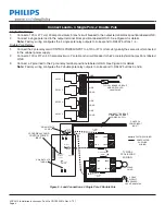
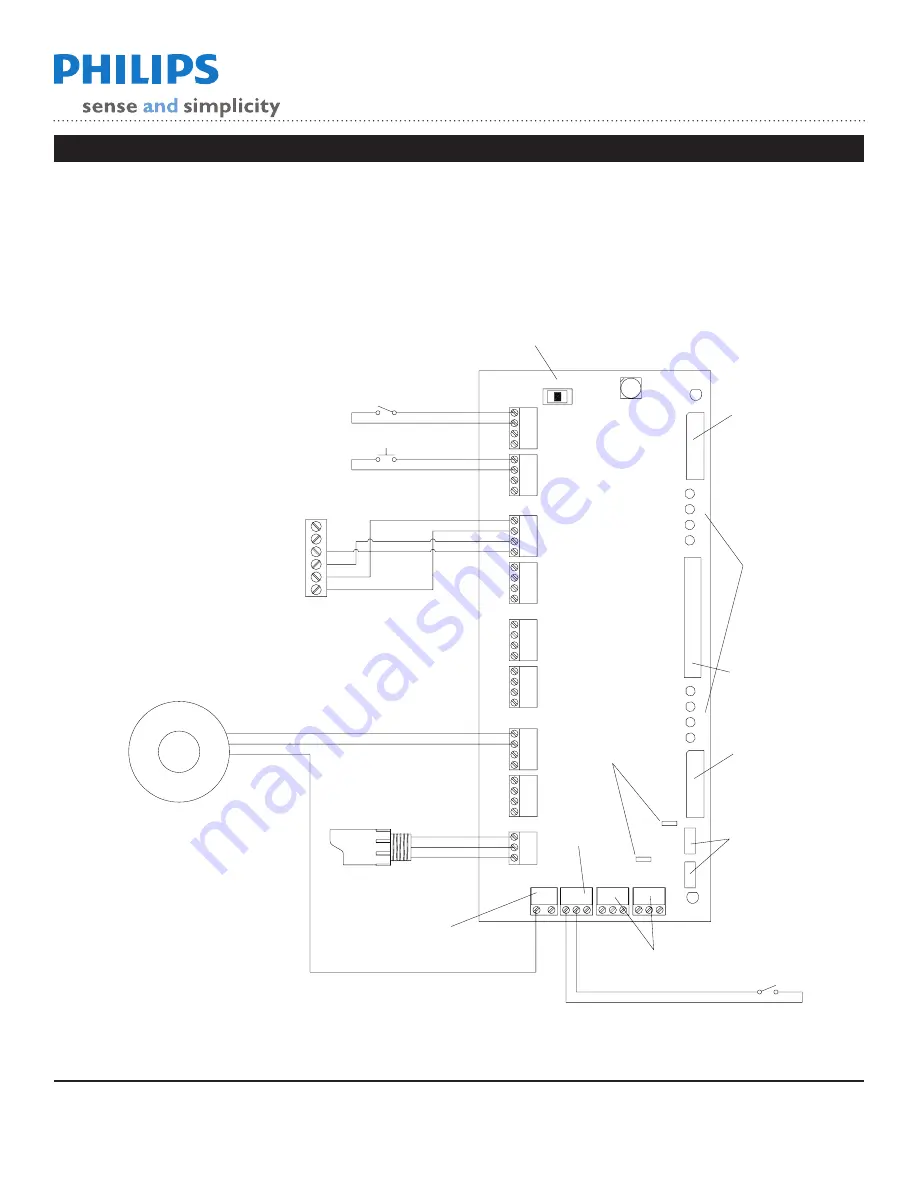
Make Low Voltage Connections
1.
If required, connect low voltage switches or other dry contact closure devices to the switch inputs. See
Figure 7
for
typical connection details.
2.
If required, connect an analog photocell to the analog photocell input. See
Figure 7
for typical connection details.
3.
If required, connect a low voltage occupancy sensor to a switch input. See
Figure 7
for typical connection details.
4.
The ON/OFF override input can be connected to a normal sense relay (SPDT), or other dry contact closure devices
and switches to provide override control of all relays. All relays (excluding any programmed as DISABLED) will be
overridden when using this input. See
Figure 7
for typical connection details.
Figure 7 - Low Voltage Connections


