background image

English

17

Automatic shutter:

up to 1/100,000 sec.

Selectable

2

):

ON, OFF, Flickerless

Manual shutter:

1/60 up to 1/10,000

Selectable

2

):

Auto Black:

ON, OFF

Selectable

2

):

Black level:

15 fixed levels

Contouring:

H and V symmetrical,

Selectable

2

):

15 fixed levels, Automatic and OFF

Compression:

White Compression

Selectable

2

):

15 fixed levels and OFF

Gamma:

Contrast Enhancement

Selectable

2

):

15 fixed level, 0.25 up to 1

Video Output

Video output 1:

BNC isolated from mechanical earth, 75 

, AC coupled,

nominal 1 V[

p-p

] CCIR or EIA composite,

Video output 2:

4 pin S-VHS connector, AC coupled
Balanced output. 2 V[

p-p

] into 150 

Unbalance -20 dB at

5 MHz

Synchronization:

Internal crystal reference, Line-locked, H/V-lock, ext V-lock

Sync. Input

BNC isolated from mechanical earth

Input impedance:

Selectable

2

): 75 

or >10 k

AC coupled

External H/V lock:

Nominal CVBS 1 V[

p-p

] (min. 150 mV, max. 600 mV)

External V-lock:

Positive V-pulse, 8%-50% duty cycle, Standard 5 V, Cmos level

Capture time:

2 s.

Serial Input/Output:

Sub D, 9-pole connector, RS 232 Selectable

2

): 1200, 2400,

4800 baud. Connector pinnings:TX=2, Rx=3, Ground=5

User input:

Switch to Mode 3, Mode select input=1, Ground=5. Pull-up 
10 k

to +5V

Selectable

2

):

Active low or active high or disable.

Lens:

DC-iris

Control & Drive 40 mA max

Video-iris

9-10 Vdc 40 mA max.Video drive level 1 V[

p-p

]

2

) Selection by PC software LTC0650/00

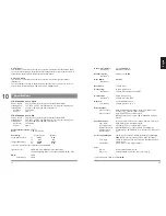
16

10

Specifications

9.2.7 H Phase
This function is active when the camera operates with external synchronisation (H+V).
Use the H-phase setting to adjust Horizontal timing differences when cameras are H-V
synchronised. Input standard CVBS synchronisation signals.

9.2.8 ext V Phase
This function is active when the camera operates with external synchronisation.
(External V)
Use the extV phase setting to adjust V phase differences when cameras are used in a
system. Input; Positive V-pulse, 8-50% duty cycle, 5 V CMOS level.

LTC 0500/10/50 models, CCIR
Pick-up Device:

752 (H) x 582 (V) active pixels, Interline Transfer CCD.

Scanning Area:

7.95 (H) x 6.45 (V) mm. Equivalent to 1/2” diagonal scanning area.

Scanning PAL:

625 lines / 50 fields / 25 frames, interlaced

Horizontal:

15.625 kHz

Vertical:

50 Hz

LTC 0500/20/60 models, EIA
Pick-up Device:

768 (H) x 494 (V) active pixels, Interline Transfer CCD.

Scanning Area:

7.95 (H) x 6.45 (V) mm. Equivalent to 1/2” diagonal scanning area.

Scanning PAL:

525 lines / 60 fields / 30 frames, interlaced

Horizontal:

15.734 kHz

Vertical:

60 Hz

Horizontal Resolution: 550 TVL
MTF:

50 % at 5 MHz

Sensitivity:

Usable Picture

Full Video

Scene illumination:

1

)

fc

0.005

0.04

lx

0.05

0.4

Imager illumination:

fc

0.0006

0.005

lx

0.006

0.05

1

) for f/1.2 lens, 89% scene reflectance and 18 dB AGC

Signal-to-Noise:

50 dB at 0.4 lux (0.04 fc) sensor illumination
(Unified weighting filter in accordance with CCIR Rec. 567)

AGC:

18 dB 

Selectable

2

):

24 dB

Summary of Contents for LTC0500

Page 1: ...ite Camera Installation manual Installationsanleitung Manuel d installation Manuale d installazione Installatiehandleiding Manual de instalación LTC0500 Subject to changes without notice Philips I C 1999 3122 165 21862 ...

Page 2: ...________________________________________ 12 7 4 Synchronisation connection Sync ____________________________ 12 7 5 Remote control connection RS 232 __________________________ 12 8 Mounting the camera________________________________________ 13 9 Operating controls and features ______________________________ 13 9 1 How to set up your camera ________________________________ 13 9 2 Function set up __...

Page 3: ...s may cause the appliance and cart combination to overturn FCC Statement 2 This device complies with Part 15 of the FCC Rules Operation is subject to the following two conditions 1 This device may not cause harmful interference 2 This device must accept any interference received including interference that may cause undesired operation This equipment has been tested and found to comply with the li...

Page 4: ...f any kind into this unit through openings as they may touch dangerous voltage points or short out parts that could result in a fire or electric shock Never spill liquid of any kind on the unit 16 Servicing Do not attempt to service this unit yourself as opening or removing covers may expose you to dangerous voltage or other hazards Refer all servicing to qualified service personnel 17 Damage Requ...

Page 5: ...External V lock H V lock Software OSD On Screen Display text is available for camera ID and set up feedback RS 232 communication Automatic image quality enhancement Auto Light Control ALC Electronic Light Control ELC allows the use of manual lenses for indoor use Non Linear Processing NLP Auto Black and Back Light Compensation BLC provide superb dynamic contrast handling for the best picture resul...

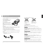
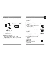
Page 6: ...ng the LVL button again or twice if the OSD menu has disappeared Use buttons for adjusting desired video level OSD indication on the right displays video level 2 1 4 3 VIDEO IRIS 4 1 2 3 2 1 4 3 DC IRIS 4 1 2 3 1 Damping coil 2 Damping coil 3 Drive coil 40 mA max 4 Drive coil Ground 5 Mounting the lens The camera supports Manual Iris Video Iris and DC Iris lenses The use of Video or DC Iris lenses...

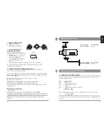
Page 7: ...era input terminal The supply connection is polarity independent Voltage range rated 11 36 V DC Power dissipation 8 W Start up current 1 A 24 V AC 12 V DC 1 2 Video Sync Balance RS232 Video Sync Balance RS232 1 2 Mains voltage models LTC0500 50 CCIR LTC0500 60 EIA Low voltage models LTC0500 10 CCIR LTC0500 20 EIA 6 Back focus adjustment The back focus screw is an endless screw that turns the back ...

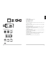
Page 8: ... from an external source sync input BNC The camera automatically configures for the applied external synchronisation For adjustment see chapter 9 7 5 REMOTE CONTROL CONNECTION RS 232 The camera can be set up using an optional Windows based PC software tool This product can be ordered separately Functions available with this software tool are AGC manual Automatic Electronic Light Control ELC Dynami...

Page 9: ...00 000 The auto setting automatically optimizes the shutter time according to the light conditions 9 2 5 Linelock setting Use this button to select between internal synchronisation and linelock The camera will switch to external lock when an external lock source is connected see 9 2 6 9 2 8 When DC is supplied the camera selects internal synchronisation 9 2 6 Linelock Phase This function is active...

Page 10: ... drive level 1 V p p 2 Selection by PC software LTC0650 00 16 10 Specifications 9 2 7 H Phase This function is active when the camera operates with external synchronisation H V Use the H phase setting to adjust Horizontal timing differences when cameras are H V synchronised Input standard CVBS synchronisation signals 9 2 8 ext V Phase This function is active when the camera operates with external ...

Page 11: ...and power cable with polarized US plug Power supply input terminals are isolated from video output terminals ENVIRONMENTAL Temperature range Operating 10 to 55 ºC 14 to 131 F Storage 40 to 70 ºC 40 to 158 F Operating Humidity 5 to 93 non condensing Electro Magnetic Compatibility Emission EN 50081 1 FCC Part 15 Class B Immunity EN 50130 4 Safety LTC 0500 10 and 50 EN 60950 LTC 0500 20 and 60 UL 650...

Reviews: