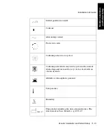


Controls and Connectors
Monitor Installation and Patient Safety 11-21
M
onitor
Ins
ta
lla
ti
on
a
nd Pa
ti
e
n
t Sa
fe
ty
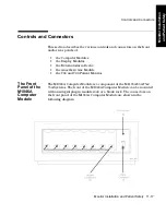
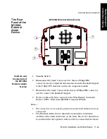
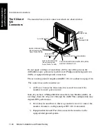
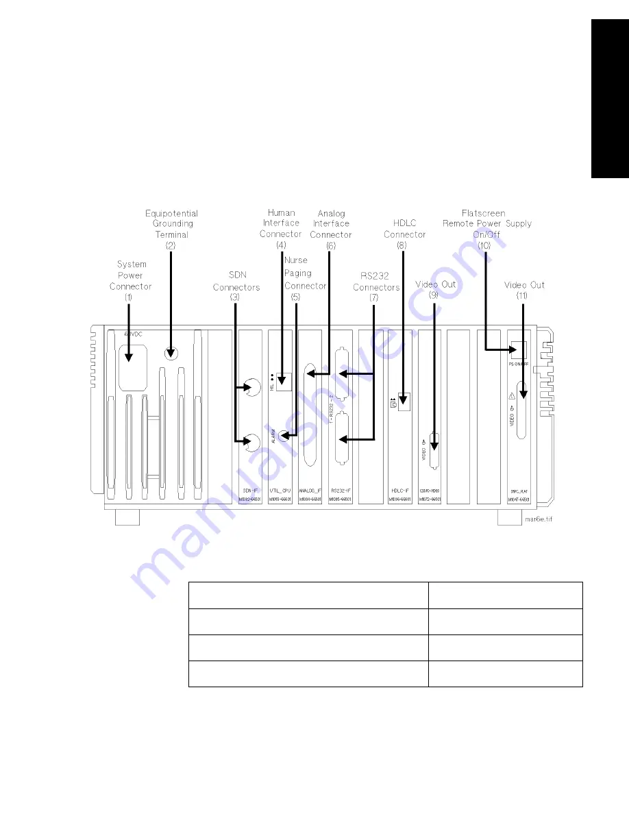
The Rear
Panel of the
M1046A/B
Computer
Modules
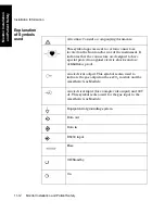
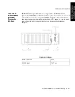
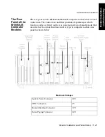
The rear panel of the M1046A and M1046B computer modules has several
connectors. The connectors, and their position, depends upon which
function cards are fitted; as the rear panel is made up of small panels that
are attached to certain function cards. A typical computer module rear
panel is shown below.
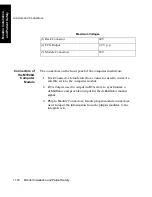
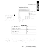
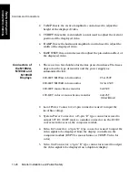
Maximum Voltages
System Power Connector
60 V
SDN Connectors
5 V
Human Interface Connector
12 V
Nurse Paging Connector
24 V
Summary of Contents for M1165
Page 12: ...Responsibility of the Manufacturer xii ...
Page 62: ...Using an ITE Display 1 40 The CMS and V24 and V26 Patient Monitors ...
Page 74: ...Attaching the Patient 2 12 Getting Started Getting Started ...
Page 172: ...Alarm Setup 5 16 Alarm Functions Alarm Functions ...
Page 228: ...Loading Paper 6 56 Recording Functions ...
Page 236: ...Admitting a Patient 7 8 Admit Discharge End Case Admit Discharge End Case OR Mode ...
Page 238: ...Admitting a Patient 7 10 Admit Discharge End Case Admit Discharge End Case endcase tif ...
Page 274: ...Drug Calculator 8 36 Trends and Calculations Trends and Calculations ...
Page 299: ...Data Transfer Module Data Transfer 10 3 Data Transfer M1235A CTS DTM CMS CMS V24 V26 ...
Page 388: ...Performance Assurance Checks 13 22 Maintenance Maintenance ...