background image

3

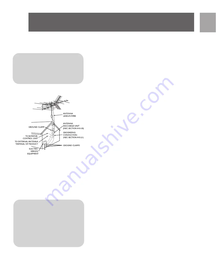
Antenna grounding and safety warn-

ing

1.Outdoor antennas and lead-in conductors from antenna

to a building, should not cross over open conductors of

electric light or power circuits. They should be kept

away from all circuits to avoid the possibility of acciden-

tal contact.

2.

Each conductor of a lead-in from an outdoor anten-

na should be connected with an antenna discharge unit.

Antenna discharge units (or Lightning Arrestor) should

be located outside the building or inside the building

between the point of entrance of the lead-in and the

TV, and as near as practical to the entrance of the con-

ductors to the building.

Important Safety Notes  

If you do not feel comfortable or competent to install this

antenna we recommend that you seek the assistance of a

qualified professional antenna installer.

Read the instructions for this device thoroughly before

attempting installation.

The installation or dismantling of any antenna near power

lines is dangerous. Each year hundreds of people are killed

or injured while attempting to install or service antennas.

For your safety and proper antenna installation, read and

follow all safety precautions. 

Choose an installation site for safety as well as perform-

ance. 

All electric power lines, cable lines and telephone lines look

alike. To be safe, assume ANY overhead line can kill you. 

Do not place an antenna where it could potentially fall on

to, or blow into a power line. If in doubt call your electric

provider. Let them review your site. 

Outdoor antennas should be grounded with an approved

E N

Safety Instructions

IMPORTANT

READ 

BEFORE INSTAL-

LATION

NEC - National Electrical Code

*

Antenna Discharge Unit is not

required if lead in conductors are

enclosed in a continuous metallic

shield that is permanently and

Warning Installation of this

product near power lines is

dangerous. For your safety,

keep ladder and antenna away

from power lines. Contact may

Summary of Contents for MANT901

Page 1: ...1 MANT901 EN User manual 3 SP Manual de utilizador 10 Manuel d utilisateur 18 FR ...

Page 2: ...2 EN Contents 3 Safety Instructions 5 Included with Antenna 5 Mounting Antenna 6 Connecting to your TV 7 Warranty 8 Technical Support ...

Page 3: ...ughly before attempting installation The installation or dismantling of any antenna near power lines is dangerous Each year hundreds of people are killed or injured while attempting to install or service antennas For your safety and proper antenna installation read and follow all safety precautions Choose an installation site for safety as well as perform ance All electric power lines cable lines ...

Page 4: ...nt Do NOT install the antenna by yourself Be sure that there are two other people available for help If any part of the antenna should come in contact with a power line DON T TOUCH IT OR TRY TO REMOVE IT YOURSELF Call your local power company immediately They will remove it Should an electrical accident occur DON T TOUCH THE PERSON IN CONTACT WITH THE POWER LINE or you too can become electrocuted ...

Page 5: ...crews 3 4 2 t Lock Washers Washers 6 4 u Wing Nuts 17 v Nuts 6 w Band Separator 1 x U Bolt 3 y Cross Piece for U Bolt Assembly 3 z Antenna Saddle 1 Quantities listed include those which may already be attached to antenna NOTE Cable mast and mounting brackets are not included Included with Assembly Note For final installation and connection of your antenna additional hardware may be required Before...

Page 6: ...wo 1 1 2 screws and wing nuts Ensure that rotation arcs in Reflector Arm Mounting Brackets face toward UHF Boom elements Attach Corner Reflector Arms to Reflector Arm Mounting Brackets by sliding Reflector Arms between Mounting Brackets Secure with 1 1 2 screw and wing nuts To fully secure Reflector Arms snap into locking tabs and tighten screws Assembly of VHF Portion Rotate reflector element rod...

Page 7: ...s well Attach tubing brace to rear of VHF Boom with 1 1 2 screws and wing nuts Slide UHF Boom through center slot of VHF Boom support block until hole A of UHF Boom aligns with hole B of VHF Boom Secure with 1 1 2 screw and wing nut Attach phasing wire and lead in wire to UHF antenna using 3 4 screws washers and wing nuts Insert end caps at ends of all booms Mast Assembly Mast not included Assembl...

Page 8: ...mbled antenna through both U bolts Face antenna toward TV station Tighten U bolts securely Wall mounts and chimney mounts are not included Lead In Wire Attach lead in wire to house with screw type stand o f f s Tighten standoffs with pliers after wire is installed Avoid sharp bends in lead in wire Form drip loop where wire enters wall Wall mounts not included Mounts mast and standoffs are not incl...

Page 9: ... the specifica tions and warnings for as long as you own this product This warranty extends only to the original purchaser of the product and is not transferable Defective products together with the dated proof of purchase must be returned to the place of purchase for repair or replace ment THERE ARE NO OTHER EXPRESS WARRANTIES Incidental and consequential damages are disclaimed where permitted by...

Page 10: ...1 0 SP Contenido 11 Instrucciones de seguridad 13 Partes incluidas 13 Para ensamblar 17 Garantía limitada por vida 17 Asistencia Técnica ...

Page 11: ...nna cerca de líneas de corriente eléctrica es peligrosa Cada año mueren o resultan heridas cientos de personas al intentar instalar o realizar el servicio de antenas Por su seguridad y para instalar correctamente la antena lea y siga todas las pre cauciones de seguridad Para elegir el sitio de instalación tenga en cuenta la seguri dad además del rendimiento Todas las líneas de corriente eléctrica ...

Page 12: ...de la antena y el cable son excelentes conductores de la corriente eléc t r i c a NO instale la antena usted solo Asegúrese de contar con otras dos personas que colaboren con usted Si cualquier parte de la antena entra en contacto con una línea de corriente NO LA TOQUE NI INTENTE QUITARLA USTED MISMO Comuníquese de inmediato con la compañía de electricidad local Ellos se encargarán de quitarla Si ...

Page 13: ...ajuste de fases 2 k Soportes del reflector 2 l Soportes del pivote 4 n Soportes de bloqueo 4 p Tapones terminales 8 q Tornillos 1 3 4 5 r Tornillos 1 1 2 10 s Tornillos 3 4 2 t Arandelas de presión Arandelas 6 4 u Tuercas de fijación 17 v Tuercas 6 w Separador de bandas 1 x Perno en U 3 y Cruceta para montaje de perno en U 3 z Carro de antena 1 Las cantidades indicadas incluyen artículos que posib...

Page 14: ...el reflec tor al soporte UHF armado paso previo usando dos tornillos de 1 1 2 y tuercas de fijación Asegurarse de que los arcos de rotación de los soportes de montaje del brazo del reflector enfrenten a los elementos del soporte UHF Incorporar los brazos en ángulo del relector a los soportes de montaje del brazo del reflector deslizando los brazos del reflector entre los soportes de montaje Asegur...

Page 15: ...delas de presión Repetir los pasos para el segundo soporte Incorporar el puntal de tubería al soporte VHF trasero con tornillos de 1 1 2 y tuercas de fijación Deslizar el soporte UHF a través de la ranura central del bloque del soporte VHF hasta que el orificio A del soporte UHF quede alineado con el orificio B del soporte VHF Asegurar con tornillo de 1 1 2 y tuerca de fijación Incorporar el cable...

Page 16: ...a la pared con tornillos de madera Colocar los soportes montados con una separación de al menos dos pies I n s e r t a r e l s o p o r t e v e r t i c a l c o n l a a n t e n a a r m a d a a t r a v é s d e l o s pernos en U Colocar la antena de frente hacia la estación de TV Ajustar los pernos en U No se incluyen soportes montados de pared ni soportes montados de chimenea Cable de derivación Inco...

Page 17: ... material manufactura o armado bajo uso normal y de acuerdo con las especificaciones y advertencias durante el tiempo que éste sea de su propiedad Esta garantía cubre úni camente al comprador original del producto y no es transferi ble Los productos defectuosos deben ser devueltos al com ercio vendedor junto con la prueba de compra que indique la fecha para su reparación o reposición NO EXISTEN OT...

Page 18: ...1 8 FR Contenu 19 Consignes de sécurité 21 Inclus avec l antenne 21 Pour Se réunir 25 Assistance technique 25 Garantie ...

Page 19: ...ement avant de procéder à l installation de cette antenne Il est dangereux d installer ou démonter cette antenne à proximité de lignes électriques Chaque année des cen taines de personnes sont tuées ou blessées en tentant d in staller ou réparer des antennes Afin d installer l antenne d une façon adéquate et sécuritaire lisez et observez ces consignes de sécurité attentivement Le choix de l emplac...

Page 20: ...sez l an tenne sur son emplacement qu une fois ce travail prélimi naire terminé Ne travaillez PAS dans des conditions humides neigeuses venteuses ni orageuses N utilisez PAS une échelle métallique Si l antenne commence à tomber laissez faire et éloignez vous N oubliez pas que le mât et le câble d antenne sont d excellents conducteurs d électricité N installez PAS l antenne si vous êtes seul Assure...

Page 21: ...che VHF A 1 d Flèche VHF B 2 e Éléments réflecteurs 2 f Élément de 46 po 1 17 m 2 g Élément de 50 po 1 27 m 2 h Jambe de force 2 j Fil de mise en phase 2 k Supports de réflecteur 2 l Supports de pivot 4 n Manettes de verrouillage 4 p Capuchons d extrémité 8 q Vis 1 3 4 po 5 r Vis 1 1 2 po 10 s Vis 3 4 po 2 t Rondelles freins Rondelles 6 4 u Écrous à oreilles 17 v Écrous 6 w Séparateur de bande 1 x...

Page 22: ...A dans la flèche UHF B et fixez à l aide d une vis 1 1 2 po et d une rondelle frein Fixez les supports de fixation du bras du réflecteur sur l assemblage de flèches UHF étape précédente à l aide de deux vis 1 1 2 po et leurs écrous à oreilles S assurer que les arcs de rotation des sup ports de fixation des bras de réflecteur sont face aux éléments de flèches UHF Fixez les bras de réflecteur de coi...

Page 23: ...50 po à la flèche VHF B Répétez chaque étape pour la flèche VHF B Insérez le bras UHF B dans le bras UHF A et fixez à l aide de vis 1 1 2 po et de rondelles freins Répétez les étapes pour la deuxième flèche Fixez la jambe de force à l arrière de la flèche VHF l aide de vis 1 1 2 po et d écrous à oreilles Faites glisser la flèche UHF à travers le centre de la fente du bloc de support de la flèche V...

Page 24: ... a l e s à l a i d e des rondelles freins et des écrous F i x e z l e s f e r r u r e s a u m u r à l a i d e d e v i s à b o i s E s p a c e z l e s f e r r u r e s d e f i x a t i o n à i n t e r v a l l e s d a u m o i n s d e u x pieds 61 cm Insérez le mât avec l antenne assemblée à travers les étri e r s Dirigez l antenne vers la station de télévision S e r r e z l e s é t r i e r s à f o n d...

Page 25: ...ande Une chaîne FM ou un second téléviseur peuvent être rac cordés à la deuxième sortie du séparateur de bande REMARQUE Le séparateur de bande n est requis que pour les téléviseurs moins récents dotés d entrées VHF UHF Pour la plupart des téléviseurs récents rac cordez simplement le câble de l antenne à l entrée F Assistance technique Courriel tech support Philips com Garantie ...

Page 26: ...2 6 Notes ...

Page 27: ...2 7 Notes ...

Page 28: ...cations are subject to change without notice Trademarks are property of Philips Accessories and Computer Peripherals 2006 Philips Accessories and Computer Peripherals Ledgewood NJ USA www philips com 313520200602 ...

Page 29: ......

Reviews: