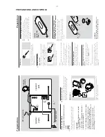
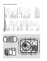


PREPARATIONS AND CONTROLS
1-8
0
!
@
9
3
*
&
^
%
5
4
6
2
#
$
2
3
1
9
6
4
5
7
8
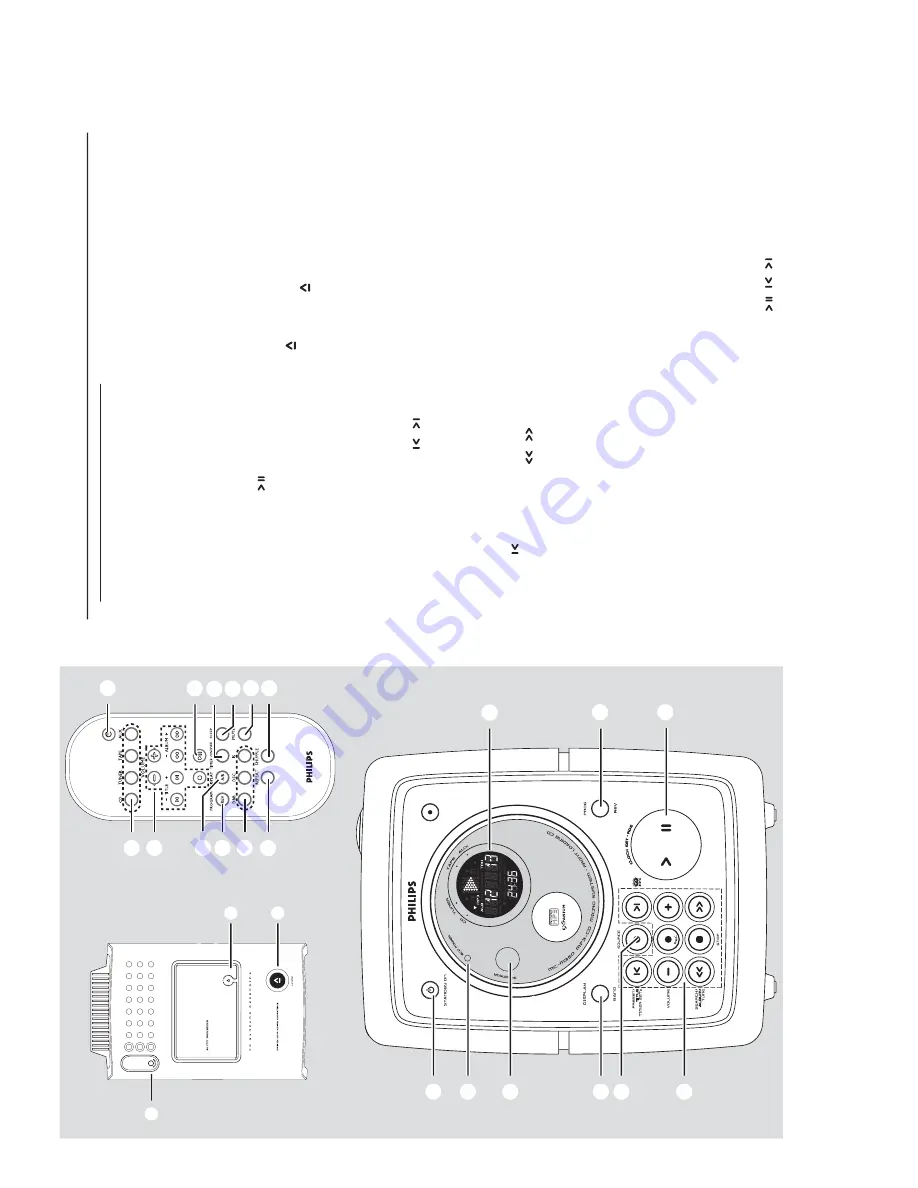
Contr
ols
Contr
o
ls on the system and
remote contr
o
l
1
Displa
y
–
sho
ws the status of the system
.
2
PR
OG/ REV
for CD/MP3-CD
......
progr
ammes tr
acks and
reviews the progr
amme
.
for
TUNER
..................
progr
ammes tuner stations
man
ually or automatical
ly
.
for
TAPE
........................
sets tape rev
er
se modes
3
CLOCK SET • RDS /
for CLOCK
.................
set the clock function.
for CD/MP3-CD
......
star
ts or inter
rupts CD
pla
yback
for
TAPE
........................
star
ts the tape pla
yback
for
TUNER
..................
displays RDS infor
m
ation
4
Mode Selection
VO
LUME (
-
/
+
)
–
adjusts the v
o
lume lev
e
l.
–
on the system only
- adjusts the hour and min
utes
for the clock/ timer functions.
PRESET/ TITLE/ TIMER
SET
/
(on
the remote control
¡
/
™
)
for
TUNER
..................
selects a preset
ra
dio station.
for CD
...........................
skips to the beginning of
a
cur
rent tr
ack/previous/ later
tr
ack
for MP3-CD
...............
to select previous/ next titl
e
for Timer
(
onl
y) to set timer under standb
y
SEARCH/ ALB
UM/
TUNE
/
(on the
remote control
11
/
22
)
for
TUNER
..................
Tune to a station
for CD
...........................
to search backward or
forward.
for MP3-CD
...............
select previous/ next album.
for
TAPE
........................
fast rewind/ wind tape
ST
OP
9
...........................................
stops CD/ MP3-CD
pla
yback or er
ase a CD
progr
amme
.
...........................................
stops tape pla
yback/
recording.
REC
.........................
star
ts recording.
5
SOURCE
–
selects the respecti
ve
sound source for CD
/
TUNER/ T
APE
/A
UX.
–
switches on the system
.
6
DISPLA
Y
-BAND
(on the remote control
DISPLA
Y
A/B
)
for
TUNER
..................
change the tuner r
adio
band.(FM/ MW/ L
W
)
for CD/MP3-CD
......
change the CD displ
ay
mode
for
TAPE
........................
switches tape direction
7
iR SENSOR
–i
nfr
ared sensor f
or remote control.
8
ECO PO
WER indicator
9
ST
ANDBY ON
2
–
switches the system to standb
y.
0
PHONES
– connects to headphone
.
!
- open/ close the cassette door
.
@
CD OPEN
–
open the CD door
.
#
INTERA
CTIVE SOUND contr
ols:
DBB
....................
(Dynamic Bass Boost) enhances
the bass.
DSC
.....................
(Digital Sound Control) selects
sound char
acter
istics:
CLASSIC/
JAZZ/ R
O
CK/ OPTIMAL.
INCREDIBLE SURR.
(IS)
.......................
creates a super
-enhanced stereo
eff
ect.
$
REPEA
T
–
repeats a tr
ack/ CD progr
amme/ entire CD
.
%
SHUFFLE
–p
la
ys CD tr
acks in r
andom order
.
^
MUTE
–i
nter
rupts and resumes sound reproduction.
&
SLEEP
–
activates/deactivates or selects the sleeper time
.
*
TIMER ON / OF
F
–
activates/deactivates the timer function.
Notes for remote control:
–
First select the source you wish to control
by pressing one of the source select keys on
the remote control (for example CD
,
TUNER).
–
Then select the desired function (for
example
,
,
).
Summary of Contents for MC-M350 SERIES
Page 12: ...2 2 2 2 ...
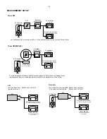
Page 14: ...4 1 4 1 SET WIRING DIAGRAM ...
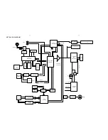
Page 16: ...CIRCUIT DIAGRAM FRONT BOARD 5 2 5 2 ...
Page 17: ...LAYOUT DIAGRAM FRONT BOARD COMPONENT SIDE 5 3 5 3 LAYOUT DIAGRAM FRONT BOARD SMD SIDE ...
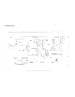
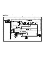
Page 20: ...6 2 6 2 CIRCUIT DIAGRAM ...
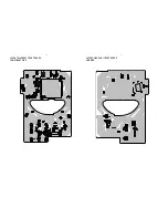
Page 21: ...6 3 6 3 POWER PCB LAYOUT ...
Page 24: ...AM FM TUNER IC TA2149BN AM FM TUNER IC TA2149BN BLOCK DIAGRAM Pins Description 7 2 7 2 ...
Page 25: ...AM FM TUNER IC TA2149BN Pins Description Pins Description AM FM TUNER IC TA2149BN 7 3 7 3 ...
Page 26: ...AM FM TUNER IC TA2149BN Pins Description AM FM TUNER IC TA2149BN Pins Description 7 4 7 4 ...
Page 31: ...DIGITAL TUNING IC TC9257F DIGITAL TUNING IC TC9257F 7 9 7 9 ...
Page 32: ...CIRCUIT DIAGRAM TUNER BOARD NON CENELEC 7 10 7 10 ...
Page 34: ...7 12 7 12 CIRCUIT DIAGRAM TUNER BOARD CENELEC ...
Page 38: ...MICROPROCESSOR TMP87EP26F MICROPROCESSOR TMP87EP26F BLOCK DIAGRAM 8 2 8 2 PINS DESCRIPTION ...
Page 39: ...8 3 8 3 MICROPROCESSOR TMP87EP26F PINS DESCRIPTION POWER DRIVER IC TA2092N ...
Page 42: ...DIGITAL SERVO PROCESSOR TC9462F BLOCK DIAGRAM 8 6 8 6 ...
Page 46: ...MICROPROCESSOR TA2153FN BLOCK DIAGRAM 8 10 8 10 ...
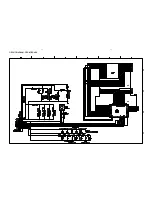
Page 47: ...CIRCUIT DIAGRAM MCU CD BOARD 8 11 8 11 ...
Page 48: ...LAYOUT DIAGRAM MCU CD BOARD COMPONENT SIDE 8 12 8 12 ...
Page 49: ...8 13 8 13 LAYOUT DIAGRAM MCU CD BOARD SMD SIDE ...
Page 52: ...9 2 9 2 CONNECTION PCB CIRCUIT DIAGRAM ...
Page 53: ...9 3 9 3 CONNECTION PCB LAYOUT DIAGRAM ...
Page 58: ...MAIN BOARD CIRCUIT DIAGRAM 10 4 10 4 ...
Page 59: ...10 5 10 5 TAPE PART CIRCUIT DIAGRAM ...
Page 60: ...MAIN PCB COMPONENT LAYOUT 10 6 10 6 ...
Page 61: ...MAIN PCB SMD LAYOUT 10 7 10 7 ...