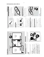
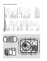


PREPARATIONS AND CONTROLS
1-9
Impor
tant notes f
or users in the
U.
K
.
Mains plug
This appar
atus is f
itted with an appro
ved 13
Amp plug.
T
o
change a fuse in this type of plug
proceed as follows:
1
Remo
ve fuse co
ver and fuse
.
2
Fix new fuse which should be a BS1362 5
Amp
,
A.S.T
.A.
or BSI appro
ved type
.
3
Ref
it the fuse co
ve
r.
If the f
itted plug is not suitab
le for y
our socket
outlets,
it should be cut off and an appropr
iate
plug f
itted in its place
.
If the mains plug contains a fuse
, this should
ha
ve
a value of 5
Amp
. If a plug without a fuse
is used,
the fuse at the distr
ibution board
should not be greater than 5
Amp
.
Note:
The se
vered plug m
ust be disposed of to
avoid a possible shoc
k hazar
d should it be
inser
ted into a 13
Amp soc
ket else
wher
e.
Ho
w to connect a plug
The wires in the mains lead are coloured with
the follo
wing code:
b
lue = neutr
al (N),
bro
wn = liv
e (L).
As these colour
s may not cor
respond with the
colour mar
kings identifying the ter
minals in
your plug,
proceed as follo
ws:
–
Connect the b
lue wire to the ter
minal
mar
ked N or coloured
bl
ack.
–
Connect the bro
wn wire to the ter
minal
mar
ked L or coloured red.
–D
o not connect either wire to the ear
th
ter
minal in the plug,
mar
ked E (or
e
) or
coloured green (or green and
ye
llo
w).
Bef
ore replacing the plug co
ve
r, m
ak
e
cer
tain
that the cord gr
ip is clamped o
ver the sheath
of the lead - not simp
ly
o
ver the tw
o wires.
Cop
yright in the U
.K.
Recording and pla
yback of mater
ial ma
y
require consent.
See Cop
yr
ight
Act 1956 and
The P
erfor
mer’
s Protection
Acts 1958 to 1972.
Norg
e
Typeskilt f
innes på appar
atens under
side
.
Obser
ve
r:
Nettbr
yter
en er sekunder
t
innk
oplet.
Den inneb
ygde netdelen er
derfor ikk
e fr
ak
oplet nettet så lenge
appar
atet er tilsluttet nettkontakten.
For å redusere faren f
or br
ann eller elektr
isk
støt,
skal appar
atet ikke utsettes for regn elle
r
fuktighet.
Italia
DICHIARAZIONE DI CONFORMI
TA
’
Si dichiar
a che l’apparecchio MC-M350 Philip
s
risponde alle prescr
izioni dell’ar
t. 2 comma 1 del
D.
M.
28
Agosto 1995 n.
548.
Fatto a Eindho
ve
n
Philips Consumer Electronics
Philips, Glaslaan
2
5616 JB Eindho
ven,
The Nether
lands
CA
UTION
Use of contr
o
ls or adjustments or
performance of pr
ocedures other than
her
ein may result in hazar
dous
radiation e
xposure or other unsaf
e
oper
ation.
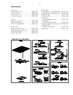
Summary of Contents for MC-M350 SERIES
Page 12: ...2 2 2 2 ...
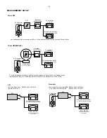
Page 14: ...4 1 4 1 SET WIRING DIAGRAM ...
Page 16: ...CIRCUIT DIAGRAM FRONT BOARD 5 2 5 2 ...
Page 17: ...LAYOUT DIAGRAM FRONT BOARD COMPONENT SIDE 5 3 5 3 LAYOUT DIAGRAM FRONT BOARD SMD SIDE ...
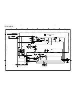
Page 20: ...6 2 6 2 CIRCUIT DIAGRAM ...
Page 21: ...6 3 6 3 POWER PCB LAYOUT ...
Page 24: ...AM FM TUNER IC TA2149BN AM FM TUNER IC TA2149BN BLOCK DIAGRAM Pins Description 7 2 7 2 ...
Page 25: ...AM FM TUNER IC TA2149BN Pins Description Pins Description AM FM TUNER IC TA2149BN 7 3 7 3 ...
Page 26: ...AM FM TUNER IC TA2149BN Pins Description AM FM TUNER IC TA2149BN Pins Description 7 4 7 4 ...
Page 31: ...DIGITAL TUNING IC TC9257F DIGITAL TUNING IC TC9257F 7 9 7 9 ...
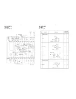
Page 32: ...CIRCUIT DIAGRAM TUNER BOARD NON CENELEC 7 10 7 10 ...
Page 34: ...7 12 7 12 CIRCUIT DIAGRAM TUNER BOARD CENELEC ...
Page 38: ...MICROPROCESSOR TMP87EP26F MICROPROCESSOR TMP87EP26F BLOCK DIAGRAM 8 2 8 2 PINS DESCRIPTION ...
Page 39: ...8 3 8 3 MICROPROCESSOR TMP87EP26F PINS DESCRIPTION POWER DRIVER IC TA2092N ...
Page 42: ...DIGITAL SERVO PROCESSOR TC9462F BLOCK DIAGRAM 8 6 8 6 ...
Page 46: ...MICROPROCESSOR TA2153FN BLOCK DIAGRAM 8 10 8 10 ...
Page 47: ...CIRCUIT DIAGRAM MCU CD BOARD 8 11 8 11 ...
Page 48: ...LAYOUT DIAGRAM MCU CD BOARD COMPONENT SIDE 8 12 8 12 ...
Page 49: ...8 13 8 13 LAYOUT DIAGRAM MCU CD BOARD SMD SIDE ...
Page 52: ...9 2 9 2 CONNECTION PCB CIRCUIT DIAGRAM ...
Page 53: ...9 3 9 3 CONNECTION PCB LAYOUT DIAGRAM ...
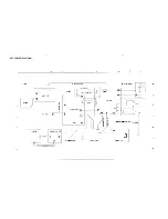
Page 58: ...MAIN BOARD CIRCUIT DIAGRAM 10 4 10 4 ...
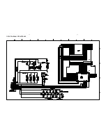
Page 59: ...10 5 10 5 TAPE PART CIRCUIT DIAGRAM ...
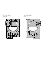
Page 60: ...MAIN PCB COMPONENT LAYOUT 10 6 10 6 ...
Page 61: ...MAIN PCB SMD LAYOUT 10 7 10 7 ...


