background image

2 - 1

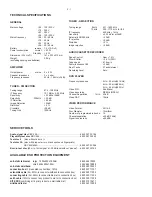
TECHNICAL SPECIFICATIONS

GENERAL

Mains voltage

-/98 : 120 / 230 V

-/96 : 120 / 230 V

-/79
-/93

-/93

:
:

:

240 V

Mains frequency

220V

-/79 :

-/98 :

50 Hz

50 Hz

-/96 : 50 / 60 Hz

50 / 60 Hz

Battery

    remote : 1.5 V (AA x 2)

Power consumption

normal :

25 W

Standby : <  4  W

Dimension (W x H x D)

: 141 x 233 x 212 mm

Weight
(excluding packing and batteries)

: 2.9 Kg

AMPLIFIER

Output power

mains : 2  x 4 W

Speaker impedance

: 2    x 4 ohm

Frequency response

: 63 Hz - 16 kHz (

±

3dB)

TUNER - FM SECTION

Tuning range

: 87.5 - 108 MHz

IF frequency

: 10.7 MHz 

±

 0.02 MHz

Sensitivity

: < 22  dBf at 26dB 

Selectivity

300kHz : > 33 dB

IF Rejection

: > 60 dB

Image Rejection

: > 25dB

Distortion  

: <  3  %

Crosstalk

: >28dB

Tuning Grid

: 100KHz

TUNER - AM SECTION

Tuning range


: 531 - 1602 kHz

            520 - 1710 kHz  for /55

IF frequency

450 kHz 

±

 1 kHz

Sensitivity 

:

 3.25 mV/m at 26dB 

:

Selectivity S9/300kHz 

: > 20 dB
:

IF rejection

: > 24 dB

Distortion 

: < 5%
:

Image rejection 

: > 28 dB

AUDIO CASSETTE RECORDER

Speed Control

: Nom

Wow & flutter

: < 0.4 % (DIN)

Tape speed

: 4.76 cm/s 

Fast wind/rewind C60

: < 39 dB 

No of Tacks
Recording Level

: 2 Tacks (stereo)
: Auto

DVD PLAYER

Frequency response

: 4 Hz – 20 kHz(44.1KHz) 

4 Hz – 22 kHz(48KHz) 
4 Hz – 44 kHz(96KHz) 

Video S/N 

: 56 dB(min)

Video decording


: MPEG-2/MPEG-1

Channel Separation             1kHz  :  40 dB 
Video DAC

: 10bits


±

1.5%

VIDEO PERFORMANCE 

Video Format

: 4:3/16:9

Disc Diameter

: 12cm/8cm

Number of programmable tracks : 16
Channel sepatation

  : 

 40dB (1KHz)

Signal to noise ratio

  : 

 65dBA

<

9kHz

10kHz

SERVICE TOOLS

Audio signal disc SBC 429.......................................................................4822 397 30184
Playability test disc SBC 444...................................................................4822 397 30245
Test disc 5

(disc without errors ) +

Test disc 5A (disc with dropout errors, black spots and fingerprints)

SBC 426/426A .....................................................................4822 397 30096

Burn in test disc (65 min. 1kHz signal at -30 dB level without “pause”) .....4822 397 30155

anti-static table mat

large 1200x650x1.25mm  

4822 466 10953

small  600x650x1.25m 

4822 466 10958

anti-static wristband

4822 395 10223

connection box (3 press stud connections, 1M

4822 320 11307

extendible cable (2m, 2M

, to connect wristband to connection box) 

4822 320 11305

connecting cable (3m, 2M

, to connect table mat to connection box) 

4822 320 11306

earth cable (1M

, to connect any product to mat or to connection box) 

4822 320 11308

KIT ESD3 (combining all 6 prior products - small table mat) 

4822 310 10671

wristband tester

4822 344 13999

AVAILABLE ESD PROTECTION EQUIPMENT

Summary of Contents for MCD 190

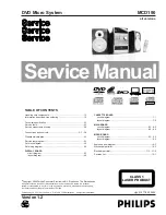
Page 1: ...ion of Philips Handling chip components 1 1 Information about lead free soldering 1 2 Technical specification 2 1 Service tools 2 1 Service measurement setup 2 2 Connections and controls 3 1 3 4 Disassembly diagram 4 1 Service test program 5 1 Set block diagram 5 2 Set wiring diagram 5 3 DISPLAY BOARD circuit diagram 6 1 layout diagram 6 2 CASSETTE BOARD circuit diagram 7 1 layout diagram 7 2 MAIN...

Page 2: ...llo stesso potenziale che quello della massa delápparecchio tramite un braccialetto a resistenza Assicurarsi che i componenti e anche gli utensili con quali si lavora siano anche a questo potenziale Safety regulations require that the set be restored to its original condition and that parts which are identical with those specified be used Safety components are marked by the symbol i Le norme di si...

Page 3: ...ies has to be purchased at external companies Special information for BGA ICs always use the 12nc recognizable soldering temperature profile of the specific BGA for de soldering always use the lead free temperature profile in case of doubt lead free BGA ICs will be delivered in so called dry packaging sealed pack including a silica gel pack to protect the IC against moisture After opening dependen...

Page 4: ...response 4 Hz 20 kHz 44 1KHz 4 Hz 22 kHz 48KHz 4 Hz 44 kHz 96KHz Video S N 56 dB min Video decording MPEG 2 MPEG 1 Channel Separation 1kHz 40 dB Video DAC 10bits 1 5 VIDEO PERFORMANCE Video Format 4 3 16 9 Disc Diameter 12cm 8cm Number of programmable tracks 16 Channel sepatation 40dB 1KHz Signal to noise ratio 65dBA 9kHz 10kHz SERVICE TOOLS Audio signal disc SBC 429 4822 397 30184 Playability tes...

Page 5: ...Ω Aerial replacement Capacitor R 50Ω Bandpass 250Hz 15kHz e g 7122 707 48001 LF Voltmeter e g PM2534 DUT S N and distortion meter e g Sound Technology ST1700B Frame aerial e g 7122 707 89001 Tuner AM MW LW To avoid atmospheric interference all AM measurements have to be carried out in a Faraday s cage RF Generator e g PM5326 Ri 50Ω Low pass filter 22kHz L R LEVEL METER e g Sennheiser UPM550 with F...

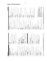
Page 6: ...3 1 1 2 7 0 ª 3 8 9 0 7 5 6 8 4 CONNECTION AND CONTROLS 1 2 7 9 8 0 5 4 3 6 DISPLAY ST ...

Page 7: ...ld the button for more than three seconds 3 4 3 CONNECTION AND CONTROLS Controls Controls on the system 1 STANDBY ON y switches the system to standby on 2 iR sensor infrared sensor for remote control 3 CLOCK Standby mode sets the system clock Playback mode displays the system clock 4 PROGRAM DVD VCD CD MP3 CD enters the program menu Picture CD during playback to select a slide show mode Tuner prog...

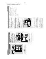
Page 8: ... impedance lower than the speakers supplied Please refer to the SPECIFICATIONS section of this manual Step 3 Antenna connection MW Antenna Connect the supplied MW loop antenna to the MW AERIAL terminal Adjust the position of the antenna for optimal reception Position the antenna as far as possible from a TV VCR or other radiation source CONNECTION AND CONTROLS Connections Step 1 Placing speakers F...

Page 9: ...ogue stereo two channel right and left recordings Recording digital C Connect the system s COAXIAL jack to the DIGITAL IN jack on a digital recording device such as DTS Digital Theatre compatible with Dolby Digital decoder Before star ting operation set the AUDIO OUT according to the audio connection See DIGITAL OUT Connecting an active subwoofer D Connect the DVD micro system s SUBWOOFER OUT jack...

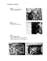
Page 10: ...3 Remove 1 screws SP3x10 A4 Remove 2 screws SP3x10 STEP B Remove Main board and LCD board B1 Remove 2 screws SP3x8 A6 A7 DISASSEMBLY DIADRAMS A5 Remove 2 screws SP3x10 A6 Remove 2 screws K3x10 A7 Remove 2 screws K3x10 B1 B2 B2 Remove 8 screws SP2 5x8 A5 A4 A3 A2 A1 DISASSEMBLY DIAGRAMS ...

Page 11: ...e PCB Assy Remove 3 screws K2x5 STEP D Remove CD tray Remove 4 screws SP3x10 STEP E Remove DVDMechaniam Remove DVD PC board 4 screws SP2 5x6 Remove CD tray cover 4 screws SP3x8 Remove DVD Mechaniam 4 screws M2 5x10 C1 D1 E3 E1 DISASSEMBLY DIAGRAMS ...

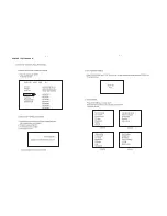
Page 12: ...5 1 5 1 SERVICE TEST PROGRAM ...

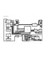
Page 13: ...5 2 5 2 SET BLOCK DIAGRAM ...

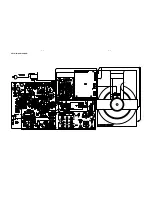
Page 14: ...5 3 5 3 SET WIRING DIAGRAM ...

Page 15: ...OTE SW211 STANDBY S10 S11 S12 S13 S14 S15 S16 S17 G11 G10 G1 G2 G3 G4 G5 G6 G7 G8 G9 D202 4148 S3 KS3 R201 4 7 0 5 C201 104 C207 47uF SW201 CH PREV SW203 TU SW204 TU SW207 CH NEXT SW208 LOUDNESS SW202 PLAY PAUSE SW205 STOP SW206 REPEAT BAND R211 10K R212 4 7K R213 10K G 1 B 2 A 3 CORD201 CORD R203 10K R204 10K R205 10K R208 10K C204 103 C203 103 RT A RT B R207 47 C206 47u C205 104 R206 10 SW210 DS...

Page 16: ...6 2 6 2 LAYOUT DIAGRAM DISPLAY BOARD ...

Page 17: ...IC301 AN7312 1 2 3 SW301A PS 62D 01 5 4 6 SW301B PS 62D 01 11 10 12 SW301D PS 62D 01 8 9 7 SW301C PS 62D 01 14 13 15 SW301E PS 62D 01 17 18 16 SW301F PS 62D 01 1 2 3 4 5 6 7 8 9 10 CN 10P TAPE MUTE TAPE R TAPE L 12V REC L GND REC R M 12V M GND REC INFO R331 2 2K R332 2 2K R316 REC 2 302 R CH 301 L CH C313 300p C312 152 R313 470 C033 393M R322 12K C322 152 C032 393M R324 39K C323 300P C031 202 C030...

Page 18: ...7 2 7 2 LAYOUT DIAGRAM CASSETTE BOARD ...

Page 19: ...W OUT L DC15V C133 1000u 16 C135 220u 16V C134 104 CD ON R143 10K D63 AN60 12V L CH R CH C126 300 C125 300 C124 300 C123 300 C122 300 5V L64 22uH DC5V 772 O N U5V 1 2 3 4 5 CN68 5P 2 5 C94 2 2u C102 10u 1 2 3 4 CN61 4P 2 0 MUTE GND C110 47u R114 47k R77 10K D60 4148 D62 4148 Q72 9014 C132 104 R151 10k D61 4148 TAPE MUTE Q65 9014 R99 10K R104 100 R98 22K R96 10 1W M Vi 1 Vo 2 GND 3 Vref 4 ON 5 IC66...

Page 20: ...8 2 8 2 CIRCUIT DIAGRAM MAIN BOARD TUNER PART ...

Page 21: ...8 3 8 3 LAYOUT DIAGRAM MAIN BOARD ...

Page 22: ...8 4 8 4 CIRCUIT DIAGRAM MAIN BOARD ...

Page 23: ... 9 E P 0 0 7 4 6 3 B F U 1 0 2 8 7 5 S 8 0 M 6 1 F U 7 4 3 0 T W 8 1 P I D 5 7 6 4 B F U 1 0 7 0 S 0 0 1 F P 0 1 7 0 E 7 3 B F U 1 0 7 4 B F U 1 0 H U 0 1 2 2 L 3 6 B F u 1 0 0 3 B F U 1 0 2 K A E J T U O I T P O 5 4 6 7 8 2 3 1 GND VCC OUT C N C N C N C N C N 8 0 E F P 0 0 1 0 4 B F U 1 0 9 3 M 10UF 16V 2 7 R K 0 0 1 6 2 M 6 1 F U 7 4 0 6 3 4 S C 3 1 U 1 2 3 4 5 6 7 8 9 0 1 1 1 2 1 3 1 4 1 5 1 6 ...

Page 24: ...7 4 9 0 M K 0 0 1 8 3 S 5 2 R 0 3 3 8 7 E F U 7 4 0 2 N C 1 2 3 4 5 1 5 2 S 2 6 E F P 3 3 K 0 2 9 6 S 4 N C A 4 H P 1 2 3 4 H U 0 1 6 0 L F U 8 6 0 0 9 4 E 9 P T A D C F P 0 8 6 5 4 E 3 Q B e p y t R 2 3 1 1 B S 2 B69 0 1UF 0 7 B F U 1 0 0 9 2 R 9 0 B F U 1 0 3 K D 8 4 1 4 N 1 F P 3 3 0 5 E 4 K D 8 4 1 4 N 1 6 K D 8 4 1 4 N 1 2 4 Q 8 1 0 3 K S 2 2 3 1 7 0 B U 1 0 F U 1 0 0 4 5 E 8 4 1 4 N 1 2 K D ...

Page 25: ... 3 2 3 3 3 4 3 7 1 8 1 5 1 6 1 9 1 7 3 8 3 9 3 2 4 5 7 8 0 1 1 1 3 1 2 4 4 4 5 4 7 4 8 4 0 5 1 5 3 5 6 3 0 2 1 7 2 8 2 1 4 2 2 0 4 3 9 3 4 9 4 6 2 1 6 4 2 5 5 3 1 2 4 5 4 1 0 A 1 A 2 A 3 A 4 A 5 A 6 A 7 A 8 A 9 A S A C S A R M Q D L E W S C E K C K L C M Q D U 0 D 1 D 2 D 3 D 4 D 5 D 6 D 7 D 8 D 9 D 0 1 D 1 1 D 2 1 D 3 1 D 4 1 D 5 1 D C N 0 A B D D V D D V S S V S S V P A 0 1 A U F R C N q D D V q...

Page 26: ...9 4 9 4 LAYOUT DIAGRAM MPEG BOARD ...

Page 27: ...10 1 10 1 1 2 3 4 5 6 7 9 10 11 12 13 18 19 20 22 23 24 25 27 26 34 35 36 37 11 12 41 42 43 51 52 53 40 EXPLODED VIEW DIAGRAM ...

Page 28: ...MPER CASSSETTE KEY 20 994000003138 SINGLE CASSETTE MECHANISM 21 994000003114 CASS PCB BKT 22 994000003131 BUTTON POWER 23 994000003112 BRACKET POWER KNOB 24 994000003128 BUTTON PROGRAM 25 994000003116 RING CD FUNCTION BUTTON 27 994000003126 BUTTON CD FUNCTION 34 994000003119 LENS CD DOOR 35 994000003109 DOOR CD 36 994000003135 CD DOOR SPRING 37 994000003107 TRAY CD 40 994000002563 DVD MECHANISM ID...
Page 29: ...ISTOR 8550C Q60 994000002545 TRANSISTOR 9014C Q62 994000002545 TRANSISTOR 9014C Q63 994000002545 TRANSISTOR 9014C Q65 994000002545 TRANSISTOR 9014C Q66 994000002545 TRANSISTOR 9014C Q67 994000002545 TRANSISTOR 9014C Q70 994000002545 TRANSISTOR 9014C Q71 994000002545 TRANSISTOR 9014C Q72 994000002545 TRANSISTOR 9014C Q501 994000002545 TRANSISTOR 9014C Q502 994000002545 TRANSISTOR 9014C IC66 9940000...

Page 30: ...CORD201 994000003173 ROT ENCODER T301 994000003174 BAIS I F T COIL T1245 DZ301 994000002516 ZENER DIODE 5V1 Q301 994000003175 TRANSISTOR BC337 25 IC301 994000003176 AN7312 SW301 994000003177 SWITCH 6P2T 994000003178 POWER TRANSFORMER 98 96 994000003186 POWER TRANSFORMER 93 994000003278 POWER TRANSFORMER 79 994000003179 DOOR LATCH SWITCH 994000003181 AC LINE CORD 98 994000003187 AC LINE CORD 93 994...

Page 31: ...se MCD190 93 96 98 79 Version 1 1 3141 785 30531 Page 5 1 MPEG software version check Update Change password 9725 to password 9735 Version 1 2 3141 785 30532 Page 8 1 Circuit Diagram Main Board Amplifier part Update Page 8 3 8 4 Layout Diagram Main Board Update ...

Reviews: