background image

Version 1.2

MCD700,  MCD702

©

 3141 785 30432

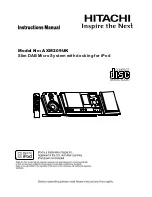
DVD Micro System

all versions 

Published by YT 0531  Service Audio    Subject to modification

© 

Copyright 2005 Philips Consumer Electronics B.V. Eindhoven, The Netherlands

All rights reserved. No part of this publication may be reproduced, stored in a retrieval
system or transmitted, in any form or by any means, electronic, mechanical, photocopying,
or otherwise without the prior permission of Philips.

Handling chip components  ........................................................... 1-1
Service tools  ................................................................................. 1-1
Leadfree and safety information ................................................... 1-2
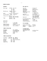
Technical specification .................................................................. 2-1
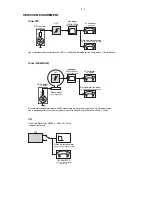
Service measurement setup ......................................................... 2-2
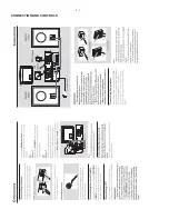
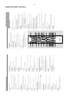
Connections and controls ..................................................... 3-1...3-3

Disassembly diagram  ........................................................... 4-1...4-2

Software version and upgrading ................................................... 5-1
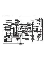
Block diagram ............................................................................... 6-1
Wiring diagram  ............................................................................. 6-2

VFD / Key Board Assembly
 circuit 

diagram 

.......................................................................... 7-1

 layout 

diagram 

.......................................................................... 7-2

DVD Block
 circuit 

diagram 

.......................................................................... 8-1

 layout 

diagram 

.......................................................................... 8-2


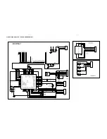
Tuner board
 circuit 

diagram. 

......................................................................... 9-1

 layout 

diagram 

.......................................................................... 9-2

DVD / MPEG board
     circuit diagram .............................................................. 10-1...10-3
 

layout diagram  ....................................................................... 10-4

AMP Block
 circuit 

diagram. 

........................................................................11-1

 layout 

diagram 

.........................................................................11-2

Exploded view diagram ............................................................... 12-1
Mechanical partslist ........................................................... 12-2...12-3

Electrical partslist .............................................................. 13-1...13-2

Revision list ................................................................................. 15-1

TABLE OF CONTENTS

MCL707

MCL707/61 partslist .......................................................... 14-1...14-2

Summary of Contents for MCD 700

Page 1: ...ols 1 1 Leadfree and safety information 1 2 Technical specification 2 1 Service measurement setup 2 2 Connections and controls 3 1 3 3 Disassembly diagram 4 1 4 2 Software version and upgrading 5 1 Block diagram 6 1 Wiring diagram 6 2 VFD Key Board Assembly circuit diagram 7 1 layout diagram 7 2 DVD Block circuit diagram 8 1 layout diagram 8 2 Tuner board circuit diagram 9 1 layout diagram 9 2 DVD...

Page 2: ...1 1 HANDLING CHIP COMPONENTS ...

Page 3: ...1 2 ...

Page 4: ...Hz 531 1602 kHz AM 10 kHz 530 1700 kHz IF frequency 450 kHz 3 kHz Sensitivity MW 4000 µV m at 26dB S N Selectivity MW 16 dB IF rejection MW 24 dB Image rejection MW 20 dB DVD MP3 CD Laser Type Semiconductor Disc Diameter 12cm 8cm Video Decoding MPEG 2 MPEG 1 Signal System PAL NTSC Video S N 53 dB min Composite Video Output 1 0 Vp p 75 S Video Output Y 1 0 Vp p 75 C 0 286 Vp p 75 Audio DAC 24 Bits ...

Page 5: ... 707 89001 Tuner AM MW LW To avoid atmospheric interference all AM measurements have to be carried out in a Faraday s cage Use a bandpass filter or at least a high pass filter with 250kHz to eliminate hum 50Hz 100Hz RF Generator e g PM5326 Ri 50 L R LEVEL METER e g Sennheiser UPM550 with FF filter S N and distortion meter e g Sound Technology ST1700B DUT CD RECORDER Use Audio Signal Disc SBC429 48...

Page 6: ...3 1 CONNECTION AND CONTROLS ...

Page 7: ...3 2 CONNECTION AND CONTROLS For more information onoperation instruction please visit Philips Audio internet site http www audio philips com ...

Page 8: ...3 3 CONNECTION AND CONTROLS ...

Page 9: ...move screws M3x4 2 pcs F Remove Display Board Assembly F1 remove screws ST 2 5x8 2 pcs take out Push Key PCB Assy A1 B1 B3 B3 B2 B1 B Remove Back Panel B1 remove screws M3x6 3 pcs B2 remove screw ST 3x10 1 pc B3 remove screws ST 3x10 6 pcs for jacks C1 C1 D1 D2 D Remove Top Cabinet D1 remove screws M3x6 3 pcs D2 remove screws M3x6 3 pcs E1 E2 E2 F1 F2 F Remove Display Board Assembly F2 remove scre...

Page 10: ...ont Cabinet E1 remove screws MK3x10 2 pcs E2 remove screws M3x4 2 pcs F Remove TFT Module for MCL707 only F1 remove screws ST 2 5x8 4 pcs A1 B2 B2 B1 B3 B Remove Back Panel B1 remove screws M3x6 3 pcs B2 remove screw ST 3x10 2 pc B3 remove screws ST 3x10 4 pcs for jacks C1 C1 D1 D2 D Remove Top Cabinet D1 remove screws M3x6 2 pcs D2 remove screws M3x6 2 pcs E2 E2 E1 F1 ...

Page 11: ...D in the CD Tray 4 TV Screen shows and upgrading will run automatically Upgrade file detected Upgrade Press PLAY to start Upgrading B CPU VERSION CHECK 1 Keep PLAY and STOP buttons on the set while plug in the power cord TV Screen shows MCD700 V1 0 TV set standard Sound Subtitle Language chosen by disk TV Screen shows 3 Press 811502 button on the remote control 3 Press oT button on the remote cont...

Page 12: ...6 1 6 1 SET BLOCK DIAGRAM ...

Page 13: ...6 2 6 2 SET WIRING DIAGRAM ...

Page 14: ...7 1 7 1 CIRCUIT DIAGRAM VFD KEY BOARD ASSEMBLY ...

Page 15: ...7 2 7 2 LAYOUT DIAGRAM VFD KEY BOARD ASSEMBLY COMPONENT SIDE ...

Page 16: ...8 1 8 1 CIRCUIT DIAGRAM DVD BLOCK ...

Page 17: ...8 2 8 2 LAYOUT DIAGRAM DVD BLOCK ...

Page 18: ... CF1 10 7M CF2 10 7M 1K R8 100k T403B CF3 450J C12 0 47uF L1 10uH R36 2 2k R35 2 2k C50 682 C51 682 R11 100 R25 1 5k R26 1 5k C16 100uF C5 3 3uF C7 3 3uF Q1 9014 Q2 9014 R27 220 R28 220 R1 47k R4 47k C15 100uF DZ1 5V1 C23 223 R22 180 J1 CON4 1 L OUT 2 GND 3 R OUT 4 9V J2 CON5 1 DO 2 CL 3 DI 4 CE 5 GND C27 203 R19 10k C38 36p X1 4 5M C32 102 24 23 22 21 20 19 18 17 16 15 14 13 1 2 3 4 5 6 7 8 9 10 ...

Page 19: ...9 2 9 2 LAYOUT DIAGRAM TUNER BOARD SIDE A SIDE B ...

Page 20: ...O S 1 2 3 0 1 1 R k 0 2 3 3 2 4 1 R 3 6 1 R k 0 1 9 1 1 R K 7 4 2 1 1 R k 1 N E P O 5 3 1 R k 0 1 7 1 1 R 0 0 1 8 1 1 R k 7 4 N E P O 2 6 C F p 0 0 2 2 F p 0 2 2 5 6 C B 5 1 U A P O 8 5 5 4 M J N 5 6 7 8 4 5 5 1 R 0 0 1 1 2 C U 1 5 3 Q D M S 5 1 0 9 C N 3 5 E C V 0 1 F u 0 1 0 8 R 0 F p 0 0 1 9 9 C 0 2 J 1 1 R E D A E H 1 2 3 4 5 6 7 8 9 0 1 1 1 8 1 U 3 3 3 5 S C C N 1 2 3 4 5 6 7 8 9 0 1 1 1 2 1 ...

Page 21: ...A 6 D A 1 D A 7 1 A 2 A 7 A D R P 0 D A 2 1 A 9 A 1 A 8 A 4 D A 7 D A 0 1 A 5 1 A C C V _ H S A L F 0 A 6 A 2 D A 8 1 A 3 D A 5 A 6 1 A R W P 4 1 A E C P 3 A 1 1 A A D S 5 2 3 0 M Q D 2 1 0 A B 2 E W 2 E C P 2 S A C 2 7 0 D A 2 S C 2 E K C D 2 D R P 2 L C S 5 2 K L C D 2 R W P 2 1 1 0 A M 2 1 3 0 Q D 2 S A R 2 1 2 0 A 2 C C V 1 5 4 3 2 1 D N G 3 3 V D 1 3 3 D S 3 3 D S 3 3 D S 3 3 D S 3 3 D S C C ...

Page 22: ... u 1 0 2 C C 0 4 P T P T C21 0 1uF 9 C F p 0 0 5 1 D M S 3 0 6 0 C 1 2 E C V 6 1 F u 7 4 3 J G N I S U O H W 1 x 4 1 2 3 4 0 5 L N E P O R 8 1 R 3 4 C F u 1 0 9 2 Q 0 5 0 8 5 2 P T 4 1 P T K 0 2 6 4 R 4 4 R 1 2 5 P T P T 1 E C v 5 2 F u 0 1 4 0 1 C F u 1 0 0 1 C F p 0 2 2 2 E C V 6 1 F u 7 4 1 J G N I S U O H W 1 x 5 0 2 P H W 5 P I D 1 2 3 4 5 7 1 E C V 6 1 F u 7 4 2 5 R k 0 1 1 0 1 P T 9 5 P T P...

Page 23: ...10 4 10 4 LAYOUT DIAGRAM DVD MPEG BOARD MPEG board is not repaired diagram for reference only ...

Page 24: ...11 1 11 1 CIRCUIT DIAGRAM AMP BLOCK ...

Page 25: ...11 2 11 2 LAYOUT DIAGRAM AMP BLOCK ...

Page 26: ...12 1 12 1 8 24 23 25 26 27 29 30 31 32 33 34 35 36 37 38 39 40 28 EXPLODED VIEW DIAGRAM AMP PART DVD PART ...

Page 27: ...LAY LENS MCL707 4 9940 000 02496 MCD700 VOL KNOB 5 9940 000 02476 MCD700 AMP CABINET FRONT 5 9940 000 03072 MCD700 AMP CABINET FRONT USA version only 6 9940 000 03089 CONDUCTIVE SPONGE 5 3 1MM 7 9940 000 02502 MCD700 AMP UNIT TOP PLATE 8 9940 000 02498 MCD700 SIDE PLATE L 8 9940 000 03075 MCD700 SIDE PLATE L USA version only 10 9940 000 02559 TOROIDAL TRANSFORMER W JTH 11 9940 000 02478 MCD700 AMP...

Page 28: ...00 03081 MCD700 DVD CABINET TOP USA version only 26 9940 000 02485 MCD700 DVD DOOR 27 9940 000 02504 CD DOOR DECORATIVE SHEET 28 9940 000 02486 LAMP CHIMNEY WHITE 29 9940 000 02488 CD DOOR LEFT BRACKET 30 9940 000 02489 CD DOOR RIGHT BRACKET 31 9940 000 02513 TUNER PCB ASS Y 32 CPU PCB ASSY see electrical partslist 33 DVD DECODER CARD ASS Y see electrical partslist 34 9940 000 02487 WORM WORM WHEE...

Page 29: ...GHT TOUCH SWITCH SW1502 9940 000 02555 LIGHT TOUCH SWITCH SW1503 9940 000 02555 LIGHT TOUCH SWITCH SW1504 9940 000 02555 LIGHT TOUCH SWITCH SW1505 9940 000 02555 LIGHT TOUCH SWITCH MISCELLANEOUS X801 9940 000 02551 CRYSTAL OSC FREQ 32 768 KHZ S701 9940 000 02542 IR SENSOR VFD701 9940 000 02541 VFD DISPLAY NE 700D 3 WR M601 9940 000 02538 MOTOR RF 370C 14370 CN801 9940 000 02552 PIN CONNECTOR 30P J...

Page 30: ...02535 VOLUME ENCODER J103 9940 000 02528 4PINS RCA SOCKET J104 9940 000 02527 SPEAKER SOCKET PST 416 J1201 9940 000 02558 SINGLE RCA SOCKET J200 9940 000 02534 HEADPHONE JACK 3 5MM SW401 9940 000 02536 SWITCH TC V030A SW402 9940 000 02536 SWITCH TC V030A 9940 000 02573 FERRITE CORE JTH16 9940 000 02532 MINI FAN RDM4010S DC12V 9940 000 02567 1 8 TFT LCD MCD707 only 9940 000 02568 1 8 TFT DRIVER PCB...

Page 31: ...4 CAB TOP PUSH KEY KNOB 9940 000 02495 MCD700 SWITCH PUSH KNOB 24 9965 000 42075 SIDE PLATE L ASH 38 9965 000 42076 SIDE PLATE R ASH 40 9965 000 42472 RUBBER FOOT MCD700 ZJ 162 9965 000 42468 DVD MECHANISM ASS Y MCD700 61 9965 000 42479 MCU PARTS ASSY MCL707 61 33 9965 000 42480 DECODER CARD ASS Y MCL707 61 31 9965 000 42471 TUNER BD ASS Y RDS MCD705 61 MECHNICAL MISCELLANEOUS PARTS FOR AMP 5 9965...

Page 32: ...AL PARTS CPU PCB D801 9940 000 02544 RECTIFIER DIODE IN5822 Q801 9940 000 02518 TRANSISTOR 8050C Q804 9940 000 02518 TRANSISTOR 8050C Q802 9940 000 02519 TRANSISTOR 8550C BD801 9940 000 02521 THYRISTOR RS406 4A U802 9940 000 02546 IC YD2576 ADJ U807 9940 000 02547 IC AT24C02 PC27 2 7V U803 9940 000 02548 IC LM7805 X801 9940 000 02551 CRYSTAL OSC FREQ 32 768 KHz CN806 9965 000 41002 SPEAKER SOCKET ...

Page 33: ...000 02528 4 PINS RCA SOCKET RCA 407 F103 9940 000 02529 FUSE F2AL250V F101 9940 000 02531 FUSE F4AL250V F102 9940 000 02531 FUSE F4AL250V 9940 000 02532 MINI FAN RDM4010S DC12V ELECTRICAL PARTS HEADPHONE PCB J200 9940 000 02534 HEADPHONE JACK 3 5MM ELECTRICAL PARTS AMP LAMP PCB LED 9940 000 02537 LED BLUE 3R4CB71D 2B 208 ELECTRICAL PARTS WOOFER OUTPUT PCB J1201 9940 000 02558 SINGLE RCA SOCKET ELE...

Page 34: ...se Version 1 1 3141 785 30431 New versions 37 79 and 96 are introduced Pages 12 1 and 12 2 Mechanical parts list adapted Pages 13 1 and 13 2 Electrical parts list adapted Version 1 2 3141 785 30432 New versions MCL707 61 Pages 14 1 14 3 part list for MCL707 61 ...

Reviews: