1
1
1
1
2
2
1
2
1
1
1
1
2
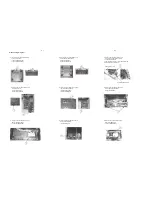
Disassembly Diagram
3-1
3-1
A,Loosen screws as below sketch map to
open the top cabinet:
1,screws:3x6BMTT(3PCS)
2,screws:3x6FMTT(2PCS)
E,Loosen screws as below sketch map to
remove the Decoder Board:
1,screws:3x10PA(3PCS)
2,screws:3x6BM(2PCS)
H,Loosen screws as below sketch map to
remove the USB Board:
1,screws:3x6PA(1PC)
I,Loosen screws as below sketch map to
remove the LAMP Board:
1,screws:2.6x4BB(2PCS)
F,Loosen screws as below sketch map to
remove the Prepositive Board:
1,screws:3x6PA(2PCS)
G,Loosen screws as below sketch map to
remove the Display Board:
1,screws:2.6x6BB(10PCS)
B,Loosen screws as below sketch map to
remove the both sides panels:
1,screws:3x6PA(6PCS)
2,screws:3x10PA(4PCS)
C,Loosen screws as below sketch map to
remove the DVD mechanism bracket:
1,screws:3x12BA(2PCS)
2,after loosed the screws, push the DVD mechanism
bracket breadthwise to remove it
D,Loosen screws as below sketch map to
remove AMP board:
1,screws:3x10PA(1PC)
2,screws:3x10PA(4PCS)
DVD mechanism bracket
Aluminium Top Cover
Summary of Contents for MCD 906
Page 9: ... 0DOIXQFWLRQ IROORZ FKHFN FKDUW ...
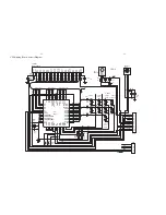
Page 14: ...5 2 5 2 VFD Display Board Layout Diagram ...
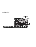
Page 16: ...Prepositive Board Layout Diagram 6 2 6 2 ...
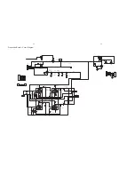
Page 18: ...7 2 7 2 AMP Board Layout Diagram ...
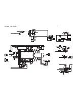
Page 22: ...Tuner Board Layout Diagram 10 2 10 2 ...
Page 31: ...11 9 11 9 Decoder Board Layout Diagram TOP ...
Page 32: ...11 10 11 10 Decoder Board Layout Diagram Bottom ...
Page 33: ...D048 12 1 12 1 Explode View for 12 37 for 12 37 for 98 for 12 ...


