

8-1
Cabinet Disassembly Instructions
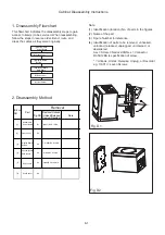
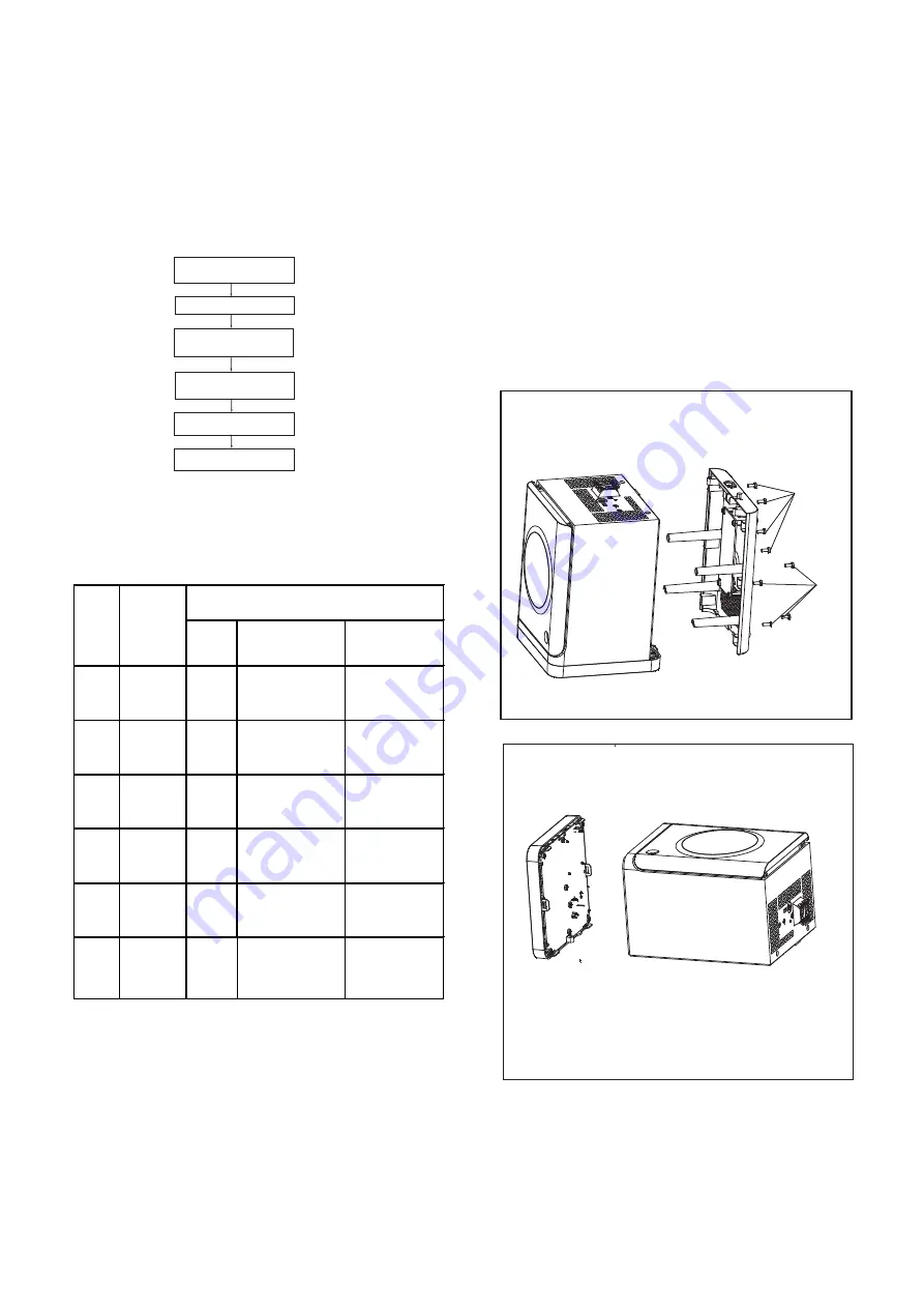
1. Disassembly Flowchart
This flowchart indicates the disassembly steps to gain
access to item(s) to be serviced. When reassembling,
follow the steps in reverse order. Bend, route, and
dress the cables as they were originally.
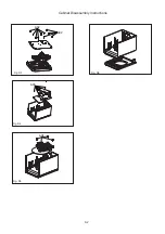
2. Disassembly Method
Note:
(1) Identification (location) No. of parts in the figures
(2) Name of the part
(3) Figure Number for reference
(4) Identification of parts to be removed, unhooked,
unlocked, released, unplugged, unclamped, or
desoldered.
Axx = Screw, CNxx/Jxx/CONxx = Connector
D3.5X12BA is specification of screw.
* = Unhook, Unlock, Release, Unplug, or Desolder
e.g. 7(A01) = seven Screws
Fig. D1
Fig. D2
Fig.NO.
Remove/Unhook
/Unlock/Release/
Unplug/Desolder
Note
8(A01) D 3 X 10 BA
[3]
Display Board
Button
D3
1 0 (A02) D3 X 10 BA
[4]
DVD Loader
Decoder Board
AMP Board
D4
[5]
D5
8 (A03) D3 X 10 BA
[3].Display Board
Button
[4].Decoder Board
AMP Board
[5].DVD Loader
[6].Front Pannel
Removal
ID/Loc.
NO.
Part
D1
[2].Front Cover
D2
[1].Bottom CAB
Power Board
[1]
Bottom CAB
Power Board
[2]
Front Cover
A01
A01
4(A04)D3 X 10 PWA
Front Pannel
[6]
D6
Summary of Contents for MCD1065/51/98
Page 24: ...8 2 Fig D3 Fig D5 Fig D4 Cabinet Disassembly Instructions Fig D6 A02 A03 A04 A02 ...
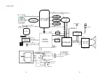
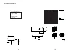
Page 28: ...Wiring Diagram Display Board Decoder Board AMP Board DVD Loader Power Board 11 1 11 1 ...
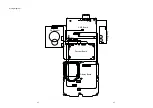
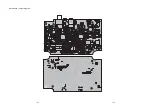
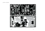
Page 31: ...AMP Board Layout Diagram 12 3 12 3 ...
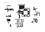
Page 33: ...Display Board Layout Diagram 12 5 12 5 ...
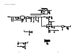
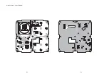
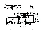
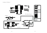
Page 35: ...Power Board Layout Diagram 12 7 12 7 ...
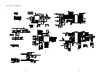
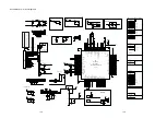
Page 42: ...Decoder Board Layout Diagram 12 14 12 14 ...
Page 44: ...Revision List Revision List Version 1 0 Initial Release 14 1 ...


