7-1
7-1
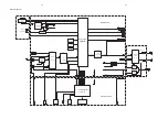
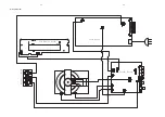
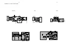
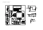
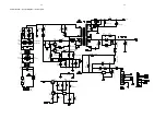
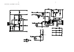
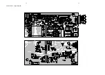
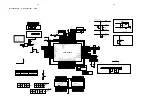
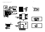
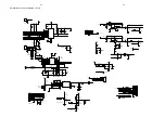
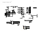
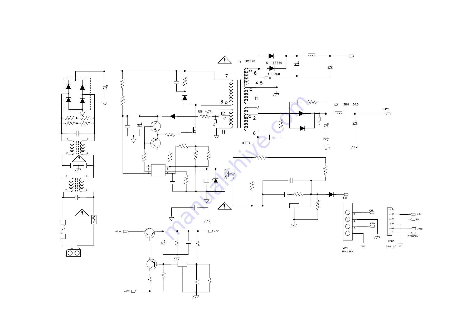
Power Board -- Circuit Diagram -- Power part
C3
68uF/400W
C11
104/50V
D6
FR104
R11
33R 5% 1206
R4
820 0805
Q10
MMBT2222
Q7
MMBT2907
R52
10R 5% 0805
R5/R68/R35/R3
1R5 5% 1206
R2
2R2 5% 1206
R36 1KR 5% 0805
C24
104/50V 0805
IC2
CYT431
R37
10K 5% 0805
D14
LL4148
C64 NC
C13
102/1KV
D9
UF5404
C14
102/1KV
C5
1000uF/10V
C1
1000uF/10V
L2
10UH
+5VA
R81
33R/1W
D10
UF5404
EL817
IC1
U1
LD7535
C20
471/50V
C19
471/50V
R21
100K/1% 0805
CY1
332/250V
C44
104/50V 0805 NC
R27
10K 1206
IC4
TL431A
Q3
D882
Q4
S8050
R17
5.1K 0805
Q1
FQPF8N60
C4
22uF/35V
R15 1M/1206
R12
1M/1206
D2 1N5408
D1 1N5408
LT
2
2.5MH
T18
LT
1
30MH UU10.5
F1 T3.15A/250V
RT
1
MF72 10D-9
D3 1N5408
D7 1N5408
R20 750K 1206
C2 103/630V
D5 FR157
D130 NC
R280
C21 1000uF/10V
R19 330R/1W
R18 5.1K/0805
R38 100K/0805
R25 3.3K 5% 0805
R79 33R/1W
C18 1000uF/25V
R44 33K 1% 0805
R42 5.1K 1% 0805
C16 1000uF/25V
R3 68K/1W
R6 750K 1206
R10 100R 5% 0805
R13
1M/1206
CX2
224/275V
R14 1M/1206
CY2
471/250V
CX1
224/275V
CON2
2.5/2P
CY3
471/250V
Summary of Contents for MCD122
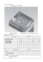
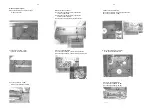
Page 15: ...6 2 6 2 LCD Display Board Layout Diagram ...
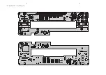
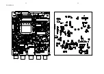
Page 18: ...Power Board Layout Diagram 7 3 7 3 ...
Page 23: ...8 5 8 5 Decoder Board ...
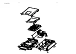
Page 24: ...9 1 9 1 Exploded View ...


