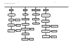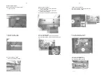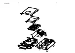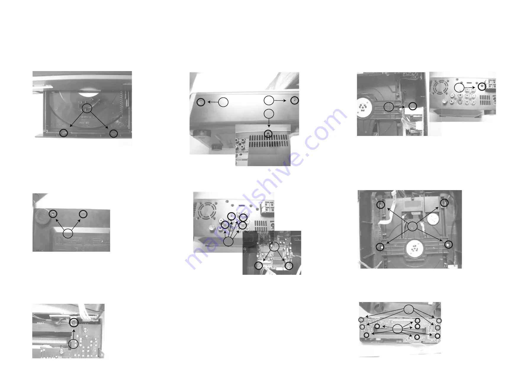
Disassembly Diagram
3-1
3-1
B.Remove the Top-cabinet
B1.Loose 2pcs screws(3 x 6 KB) of both side
near to the back side.
B2.Loose 2pcs screws(3 x 8 Km) of both side
near to the front cabinet.
B3.Loose 1pc screw(3 x10 FA) of the back side.
C.Remove the Power Board
C1.Loose 1pc screw(3 x10 FA) of the back side.
C2.Loose 1pc screw(3 x 8 BA)
E.Remove Decoder Board
E1.Loose 4pcs screws(3 x 10 FA) of the back side.
E2.Loose 2pcs screws(3 x 10 FA) of the decoder board.
D.Loose 4pcs screws(3 x 10 PWA)
to remove DVD Loader Driver
F.Loose 2pcs screws(3 x 8 FT)
to remove the Front Cabinet
G.Loose 1pc screw(3 x 8 BA)
to remove the Headphone Board
A.Open the DVD Door and loose 2 clipps
to remove the door
H.Remove the Display Board
H1.Loose 6pcs screws(3 x 8 BA)
H2.Loose 4pcs screws(2 x 8 BT)
A
B1
B2
B3
C1
C2
D
E1
E2
F
G
H2
H1
Summary of Contents for MCD122
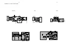
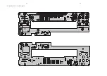
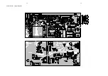
Page 15: ...6 2 6 2 LCD Display Board Layout Diagram ...
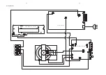
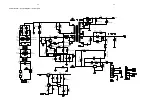
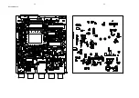
Page 18: ...Power Board Layout Diagram 7 3 7 3 ...
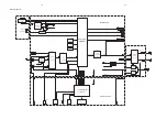
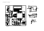
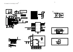
Page 23: ...8 5 8 5 Decoder Board ...
Page 24: ...9 1 9 1 Exploded View ...

