background image

2-1

2-1

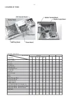
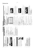
DISMANTLING INSTRUCTIONS

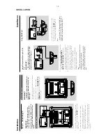
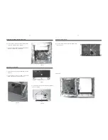
Dismantling of the PCB assemblies and modules

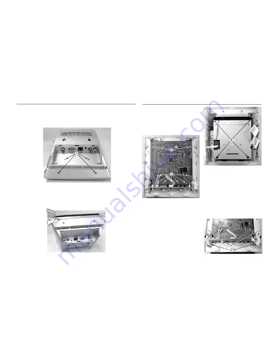
1) Loosen 4 screws B  to remove DVD Loader as shown in

Figure 3.

2) Loosen 2 screws C and 7 screws D to remove the Display

Board as shown in Figure 4.

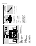
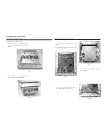
Dismantling of the Front Panel assembly

1) Loosen & remove 4 screws A (see figure 1).

2) Place a small flat screw driver in between the front & rear

cabinets and roll the screw driver along the joint as shown

in figure 2.

Figure 2

Figure 1

Figure 3

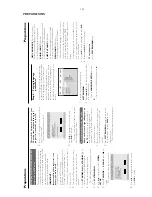
3) Release total 6 catches on left and right side  of  rear

cabinet to separate it from the rear assembly.

3) Loosen 2 screws E to remove the AMP Key Board as

shown in Figure 4.

Figure 4

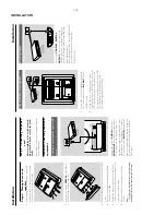
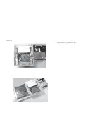
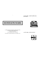
4) Loosen 2 screws F and 4 screws G and 2 screws H to

remove Swing System as shown in Figure 5.

Figure 5

Summary of Contents for MCD288

Page 1: ...ay Board AMP Key Board 6 Tuner Board 7 Power Board 8 Woofer Output Board 9 Scart Board 10 Set Mechanical Exploded View Parts List 11 Electrical Parts List 12 Revision List 13 Copyright 2009 Philips Consumer Electronics B V Eindhoven The Netherlands All rights reserved No part of this publication may be reproduced stored in a retrieval system or transmitted in any form or by any means electronic me...

Page 2: ...x Surround RDS x News x Dolby Pro Logic DPL Incredible Surround Karaoke Features Voltage Selector x ECO Power Standby VFD Display Off x x ECO6 Tuner Board Systems Non Cenelec ECO6 Tuner Board Systems Cenelec USB Direct VERSION VARIATIONS Type Versions MCD288 Features Board in used x 12 98 x x x x x x x x x x x LOCATION OF PCBS ...

Page 3: ...thin 1 0dB 20Hz 20kHz Signal Noise ratio A weighted 70dBA Channel Unbalance 2dB Vol 0 _ 50dB Channel Separation 1K 40dB THD Noise 20 20 000Hz at 1kHz 0 5 De emphasis 0 or 15 50 µS Switched automatically by CD10 MPEG 1 Layer 3 MP3 CD MPEG AUDIO MP3 CD Bit Rate 8 320 kbps MP3 CD Sampling Frequencies 8k 11 025k 16k 22 05k 32k 44 1k 48k Hz Recording Format ISO 9660 UDF format not supported USB Measure...

Page 4: ...es has to be purchased at external companies Special information for BGA ICs always use the 12nc recognizable soldering temperature profile of the specific BGA for de soldering always use the lead free temperature profile in case of doubt lead free BGA ICs will be delivered in so called dry packaging sealed pack including a silica gel pack to protect the IC against moisture After opening dependent...

Page 5: ...ection Connect the supplied FM antenna to the FM AERIAL terminal Fully extend and adjust the position of the antenna for optimal reception For better FM stereo reception connect an outdoor FM antenna to the FM AERIAL FM ANTENNA terminal Notes This system does not support MW reception Installation Step 1 Connecting speakers 1 Place the main set with the front side facing down on a flat and firm sur...

Page 6: ...t by matching the pins Installation Using Component Video jacks Y Pb Pr IMPORTANT The progressive scan video quality is only possible when using Y Pb Pr and a progressive scan TV is required R 1 Use component video cables red blue green to connect the COMPOENT VIDEO OUTPUT Pr Cr Pb Cb Y jack to the corresponding Component video input jacks or labeled as Y Pb Cb Pr Cr or YUV on the TV 2 If you are ...

Page 7: ...ck of a non USB device AUDIO OUT L R VCR for example Connect the system s AUX IN jack to the AUDIO OUT jacks on another audio visual device such as a VCR Laser Disc player or cassette desk using a single to double cinch cable with one end providing a 3 5 connector for connection to the AUX IN jack while the other end providing two white red connectors for connection to the other device s AUDIO OUT...

Page 8: ...enjoy the device s stored music through the powerful speakers of Hi Fi system Insert the USB device s USB plug into the socket on the set for the devices with USB cables 1 Insert one plug of the USB cable not supplied to the socket on the set 2 Insert the other plug of the USB cable to the USB output terminal of the USB device for the memory card 1 Insert the memory card into a card reader not sup...

Page 9: ...played on the whole TV screen with a portion automatically cut off 4 3 LB Letterbox mode If you have a conventional TV set and your DVD is formatted for widescreen viewing use this setting A wide picture with bands displayed on the upper and lower portions of the TV screen 16 9 Wide screen mode If you have a widescreen TV set use this setting you must also set your widescreen TV to full size avail...

Page 10: ...ve signals and progressive is set by mistake You must reset the unit to interlace format 1 Turn off your TV progressive scan mode or turn on to interlaced mode refer to your TV user manual 2 Press SYSTEM MENU on the remote to exit the system menu and then DISC to exit progressive scan The DVD blue background screen will appear Preparations OSD LANGUAGE On Screen Display Switches the display langua...

Page 11: ... ejects a disc from the disc loader 0 AUX IN connects an external non USB device USB DIRECT jack for the external USB mass storage device SLIDE OPEN 4 slides down to expose some buttons and jacks on the front panel Controls on the remote control 1 STANDBY y to switch the system on or to Eco power normal standby mode 2 Numeric Keypad 0 9 inputs a track title chapter number of the disc 3 PROGRAM DVD...

Page 12: ...emote control First select the source you wish to control by pressing one of the source select keys on the remote control DISC or TUNER for example Then select the desired function 2 for example Press and hold the button for more than three seconds w w w WARNING Under no circumstances should you try to repair the system yourself as this will invalidate the warranty Do not open the system as there ...

Page 13: ...USE 2 to resume the normal play mode Make sure the MP3 CD was recorded within 32 256 kbps bit rate with sampling frequencies at 48 kHz 44 1 kHz or 32 kHz Ensure that the DTS disc also supports Dolby Digital output If the signal is too weak adjust the antenna or connect an external antenna for better reception Increase the distance between the System and your TV set or VCR Troubleshooting Problem S...

Page 14: ... remove 4 screws A see figure 1 2 Place a small flat screw driver in between the front rear cabinets and roll the screw driver along the joint as shown in figure 2 Figure 2 Figure 1 Figure 3 3 Release total 6 catches on left and right side of rear cabinet to separate it from the rear assembly 3 Loosen 2 screws E to remove the AMP Key Board as shown in Figure 4 Figure 4 4 Loosen 2 screws F and 4 sc...

Page 15: ... to separate it from the Rear panel Dismantling of the Subwoofer 1 Use the flat screw driver prize up 4 rubber pads as shown in Figure 6 2 Loosen 4 screws J to remove two subwoofer feet on the bottom of the subwoofer as shown in Figure 7 Figure 7 Figure 6 3 Loosen 10 screws K to remove the Subwoofer Output Pan as shown in Figure 8 Figure 8 Dismantling of the Subwoofer 4 Loosen 10 screws L to remov...

Page 16: ...Service pos B Note After re assembly it is very important to ensure all wires are routed properly to ensure that they do not touch obstruct all moving parts Service pos C 2 3 2 3 ...

Page 17: ...s the Production Date 200X XX XX 38 Button pressed Y N V refers to Version XX refers to Software version number of the uProcessor eg 04 200X XX XX refers to Date eg 2006 02 22 9735 Buttons on RC pressed sequentially Y N TV Display shows To check MPEG software version hold the System Menu button on Remote Control Select SYSTEM SETUP on TV display Ver MCD288 XXXX Date mm dd yyyy Time hh mm ss Region...

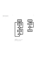
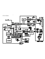
Page 18: ...4 1 SET BLOCK DIAGRAM 4 1 ...

Page 19: ...5 1 SET BLOCK DIAGRAM 5 1 ...

Page 20: ...gram and Printed Circuit Board drawings are published for orientation only In case of defects please replace the entire board The Display Board and AMP Key Board can be ordered with codenumber 9940 000 04868 9940 000 04869 for 37 6 1 6 1 DISPLAY AMP KEY BOARD LAYOUT DIAGRAM AMP KEY BOARD ...

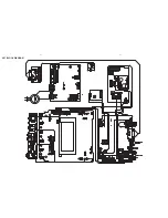
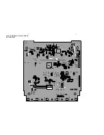
Page 21: ...6 2 6 2 LAYOUT DIAGRAM DISPLAY BOARD TOP VIEW ...

Page 22: ...LAYOUT DIAGRAM DISPLAY BOARD BOTTOM VIEW 6 3 6 3 ...

Page 23: ...ET SW102 TU R101 22K R102 10K R103 4 7K R104 100 5v R334 10K LED302 E LED301 E LED304 E LED303 E LED306 E LED305 E Q305 8050 R346 1K C331 100uf 16v R345 4 7K D306 4148 12V R352 680 R351 680 R350 680 R349 680 R348 680 R347 680 VF1 1 VF1 2 G1 3 G6 4 G5 5 G4 6 G3 7 G2 8 G12 9 G7 10 G8 11 G9 12 G10 13 G11 14 S1 15 S2 16 S3 17 S4 18 S5 19 S6 20 S7 21 S8 22 S9 23 S10 24 S11 25 S12 26 S13 27 S14 28 S15 2...

Page 24: ...omponent level Circuit Diagram and Printed Circuit Board drawings are published for orientation only In case of defects please replace the entire board The board can be ordered with codenumber 9940 000 04875 7 1 7 1 PCB LAYOUT TOP VIEW TUNER BOARD ...

Page 25: ...EN 9 BUSE 10 SWP1 11 SWP2 12 XTL1 13 XTL2 14 PHFL 15 PIFL 16 VAFR 17 VAFL 18 TMUT 19 MPXO 20 VREF 21 TIFC 22 LDE1 23 LDE2 24 IGAN 25 AGND 26 VCCA 27 RFI1 28 RFGD 29 RFI2 30 TAGC 31 LOOPSW 32 U1 TEA5768HL C4 472p R7 100K L1 33nH L2 33nH C7 223p C8 103p R1 22 XT1 13MHz R10 10K R8 10K C9 223p C22 474p C16 333p C23 474p C17 330pF C13 223p C18 333p C14 223p C15 102p R2 10 C19 473p C20 473p C21 473p C24...

Page 26: ...paired on component level Circuit Diagram and Printed Circuit Board drawings are published for orientation only In case of defects please replace the entire board The Power Board can be ordered with codenumber 9940 000 04865 for 37 8 1 8 1 POWER BOARD ...

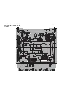
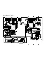
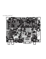
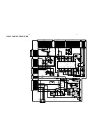
Page 27: ...8 2 8 2 LAYOUT DIAGRAM POWER BOARD ...

Page 28: ...0uf 16v C203 104M C202 104M D205 5401 D206 5401 D207 5401 D208 5401 C290 3300uf 35v C287 104p D211 4001 D209 4001 C289 330uf 35v C288 104p CPU VCC CPU VCC ECO POWER F201 F2AL250V D212 4148 12V R259 1 5A AGND DVD MUTE DVD MUTE 1 2 3 4 5 6 7 8 9 10 11 12 13 14 15 16 CN210 7p 2 0 DGND DM DP U5V WP SD3V DGND SENSE SD_D3 SD_D1 SD_D2 SD_BS SD_CLK SD_D0 1 2 3 4 5 6 CN205 6p 2 0 1 2 3 4 5 6 7 8 9 10 11 12...

Page 29: ...rinted Circuit Board drawings are published for orientation only In case of defects please replace the entire board The Power Board can be ordered with codenumber 9940 000 04871 for 37 9 1 9 1 WOOFER OUTPUT BOARD LAYOUT DIAGRAM WOOFER TERMINAL BOARD 9940 000 04873 LAYOUT DIAGRAM WOOFER LAMP BOARD ...

Page 30: ...9 2 9 2 LAYOUT DIAGRAM WOOFER OUTPUT BOARD ...

Page 31: ...60 R555 36K R554 4 7 0 25 R558 4 7 0 25 C524 562 M C523 104 M C526 104 M C522 4 7uf 25v L502 2uH L501 2uH MUTE1 Vcc OUT2 OUT1 1 2 CN507 3P 2 0 C527 104p VCC Q510 9014 R539 6 8K R540 47K D501 4148 R538 4 7K R541 2 2K R544 10K MUTE R SP L SP VF1 VF2 28V GND 1 2 3 4 5 6 7 8 9 10 11 12 13 14 15 16 CN503 VGV 15P 16 5v2 16 5v1 GND L CPU VCC ECO POWER STBY R GND GND MUTE2 1 R SP 1 L SP 1 VF1 1 VF2 1 28V ...

Page 32: ...3 ELEC CAP 4700µF 35V DB1 9940 000 03502 THYRISTOR RS808 IC1301 9940 000 03767 IC TDA7265 STEREO POWER IC IC501 9940 000 04669 IC TL072 IC504 9940 000 04976 IC TDA7264 Q502 9940 000 04974 TRANSISTOR 8550 C Q508 9940 000 02545 TRANSISTOR 9014C Q509 9940 000 02545 TRANSISTOR 9014C Q510 9940 000 02545 TRANSISTOR 9014C Note Only these parts mentioned in the list are normal service parts 9 4 9 4 ...

Page 33: ...he Video Output Board can be ordered with codenumber 9940 000 04874 for 37 The Scart Board can be ordered with codenumber 9940 000 04985 for 12 10 1 10 1 SCART VIDEO OUTPUT BOARD LAYOUT DIAGRAM VIDEO OUTPUT BOARD LAYOUT DIAGRAM SCART BOARD 1 5 4 3 2 6 JACK702 RCA3P 1 2 3 4 5 6 7 8 9 10 CN701 10P 1 3 2 4 JCK701 RCA 206V 1 2 3 4 5 6 7 JACK703 S VIDEO R SC G Y B U CVBS SPIDF M L M R RGB SW 16 9 VS GN...

Page 34: ...11 1 11 1 SET MECHANICAL EXPLODED VIEW 08 12 06 01 02 05 03 04 13 07 15 11 09 15 14 17 18 19 28 26 27 21 22 24 23 25 10 16 20 X4 ...

Page 35: ... 04896 BACK CABINET 37 19 9940 000 05005 BACK CABINET 12 93 98 20 9940 000 04924 SPK ORIENTATION RUBBER 21 9940 000 04894 SLIDE DOOR SPRING R 22 9940 000 04904 PUSH DOOR BKT 23 9940 000 04907 SWING ARM 24 9940 000 04906 DOOR LIP 25 9940 000 04893 SLIDE DOOR SPRING L 26 9940 000 04898 FOOT BACK COVER 27 9940 000 05422 FOOT 28 9940 000 04897 FOOT FRONT COVER 9940 000 04882 SUBWOOFER FOOT BOTTOM 9940...

Page 36: ...H SWITCH SW308 9940 000 02543 LIGHT TOUCH SWITCH SW309 9940 000 04964 LIGHT TOUCH SWITCH SW310 9940 000 04964 LIGHT TOUCH SWITCH SW311 9940 000 02543 LIGHT TOUCH SWITCH SW312 9940 000 02543 LIGHT TOUCH SWITCH X302 9940 000 03152 FILTER FREQ 4 19MH X303 9940 000 04962 CRYSTAL 4 332MHZ 12 Note Only these parts mentioned in the list are normal service parts ELECTRICAL PARTS LIST POWER BOARD C290 9940...

Page 37: ...971 CAP 334J 100V C524 9940 000 04972 MYLAR CAP 5600P 100V C560 9940 000 04973 ELEC CAP 4700µF 35V C561 9940 000 04973 ELEC CAP 4700µF 35V DB1 9940 000 03502 THYRISTOR RS808 F501 9940 000 03433 FUSE F6 3A L250V F502 9940 000 03433 FUSE F6 3A L250V IC1301 9940 000 03767 IC TDA7265 IC501 9940 000 04669 IC TL072 IC504 9940 000 04976 IC TDA7264 Q502 9940 000 04974 TRANSISTOR 8550 C Q508 9940 000 02545...

Page 38: ... J104 9940 000 04966 HEADPHONE JACK D3 5 J105 9940 000 04967 AUX IN JACK CK3511 J106 9940 000 04968 USB JACK A TYPE 4P LED101 9940 000 02537 LED BLUE LED102 9940 000 02537 LED BLUE SW101 9940 000 04965 LIGHT TOUCH SW KFC 05 SW102 9940 000 04965 LIGHT TOUCH SW KFC 05 SW103 9940 000 04965 LIGHT TOUCH SW KFC 05 SW104 9940 000 04965 LIGHT TOUCH SW KFC 05 Note Only these parts mentioned in the list are...

Page 39: ...dated 1 3 Manual 3141 785 30803 In this version Version 05 added Page 11 2 Mechanical Accessories Parts List updated 1 4 Manual 3141 785 30804 In this version DVD Decorder Board has been divided into 5 items as per separate version Page 11 2 Mechanical Accessories Parts List updated 1 5 Manual 3141 785 30805 In this version Page 11 2 Mechanical Accessories Parts List updated Add 9965 100 17680 DIS...

Reviews: