3 - 3
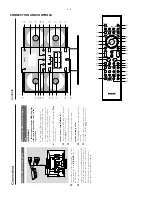
CONNECTION AND CONTROLS
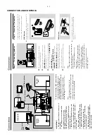
Using the
VCR f
or r
ecor
ding D
VDs
CONNECT
T
O
SUB WOOFER
R
L
SPEAKERS 6
Ω
Y/Pb/Pr OUT
A/V OUT
A
UDIO IN
L
R
VIDEO IN
VCR
1
Connect the end of the supplied
A
V
cord with
onl
y one connector to the
A/V OUT
jack of
the D
VD system.
2
For the other end, connect the video output
connector (y
ello
w) to the
VIDEO IN jack on the
VCR and the audio connector
s (white/ red) to
the cor
responding audio input jacks on the
VCR.
This will allo
w y
ou to mak
e analogue stereo
(tw
o channel,
r
ight and left) recordings.
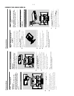
Connecting a USB de
vice or memor
y
car
d
IMPOR
T
ANT!
–
Bef
or
e connecting the USB plug,
first
slide open the pr
otective co
v
er on the
sock
et.
By connecting a USB mass stor
age device
(including USB flash memor
y, USB flash pla
ye
rs
or memor
y cards) to the Hi-Fi system,
y
ou can
enjo
y the device's stored m
usic through the
po
w
erful speak
er
s of Hi-Fi system.
●
Inser
t the USB device's USB plug into the
sock
et on the set.
for the de
vices with USB cables:
1
Inser
t one plug of the USB cable (not supplied)
to the
sock
et on the set.
2
Inser
t the other plug of the USB cab
le to the
USB output ter
minal of the USB device
.
for the memor
y car
d:
1
Inser
t the memor
y card into a card reader (not
supplied).
2
Use a USB cab
le (not supplied) to connect the
card reader into the
sock
et on the set.
1
7
3
9 6
@
!
7
9
#
7
2
5
7
9
4
0
8
9
1
&
(
5
0
%
@
*
2
3
$
7
9
)
4
(
8
8
6
#
≤
!
¡
∞
§
^
£
≥
™
7
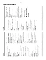
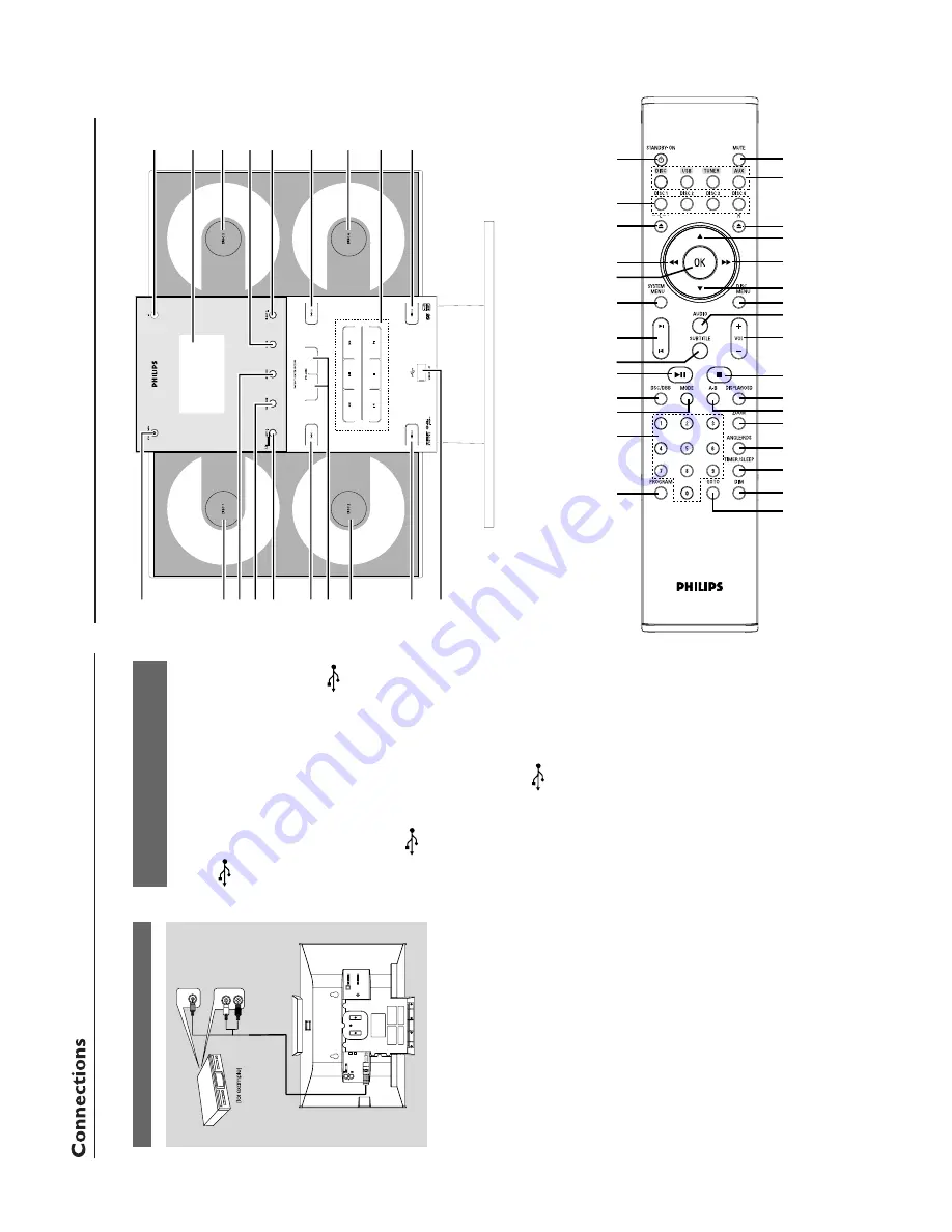
Controls
Summary of Contents for MCD299
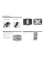
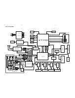
Page 14: ...WIRING DIAGRAM 5 2 5 2 ...
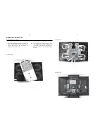
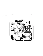
Page 18: ...LAYOUT DIAGRAM AMP PCB 7 2 7 2 ...
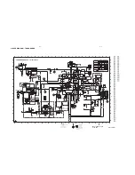
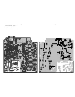
Page 27: ...LAYOUT DIAGRAM MAIN PCB TOP 8 9 8 9 ...
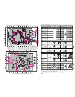
Page 28: ...LAYOUT DIAGRAM MAIN PCB BOTTOM 8 10 8 10 ...
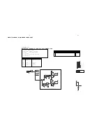
Page 29: ...LAYOUT DIAGRAM VIDEO PCB USB PCB VGA PCB USB PCB VGA PCB VIDEO PCB 8 11 8 11 ...
Page 31: ...LAYOUT DIAGRAM DISPLAY PCB 9 2 9 2 ...

