1-10
Troubleshooting
The aspect ratio of the scr
een cannot be
chang
ed e
ven though y
ou ha
ve set the
TV
sha
pe.
No sound or distor
ted sound.
The micr
o D
VD pla
y
er does not star
t
pla
yback.
The D
VD micr
o system does not
respond when the buttons ar
e pr
essed.
Cannot activate some f
eatur
es,
such as
Angles,
Subtitles,
or m
ulti-langua
ge
Audio
.
Considerable noise in radio br
oadcasts.
Sound cannot be hear
d or is of poor
quality
.
The aspect ratio is f
ix
ed on the D
VD disc
.
Depending on the
TV
, it ma
y not be possible to
change the aspect r
atio
.
Adjust the v
olume
.
Check that the speak
er
s are connected
correctl
y.
Replace the speak
er cab
les.
Disconnect the headphones.
The system is in pause
, slo
w motion or fast
forward/rev
er
se mode
, press
(or
on the remote) to resume nor
mal pla
y mode
.
Inser
t a readab
le disc with the pla
yback side
facing do
wn.
Check the disc type
, colour system and regional
code.
Check f
or an
y scr
atches or sm
udges on
the disc
.
Press SYSTEM MENU to turn off the setup
men
u screen.
Cancel the parental control r
ating function or
change the rating level.
Moisture has condensed inside the system.
Remo
ve
the disc and lea
ve
the system turned
on f
or about an hour
.
Disconnect the po
w
er plug from the outlet and
inser
t again.
Multi-language sound or subtitle is not
recorded on the D
VD
.
Changing the language f
or the sound or subtitle
is prohibited on the D
VD
.
The f
eatures ma
y not be a
vailab
le on the disc
.
Tune in to the correct frequency
.
Connect the antennas.
Full
y extend the FM wire antenna.
P
osition f
o
r
best reception and secure to a wall.
Connect an outdoor FM or
AM antenna.
Adjust the direction and position f
or best
reception.
Place the antenna far
ther a
w
ay
from any
equipment that ma
y be causing the noise
.
Increase the distance betw
een the system and
your
TV or other equipment.
Tr
oub
leshooting
2
2
W
ARNING
Under no circumstances should you tr
y to repair the system your
self,
as this will in
validate the
w
arr
anty
. Do not open the system as ther
e is a risk of electric shock.
If a f
ault occur
s,
fir
st check the points listed belo
w befor
e taking the system for repair
. If you
ar
e unable to r
emedy a pr
oblem b
y
follo
wing these hints
, consult your dealer or Philips for
help.
Tr
oub
leshooting
Pr
ob
lem
Solution
No po
w
e
r.
No pictur
e
.
Distor
ted or poor picture
.
Completel
y distor
ted pictur
e or black/
white pictur
e
.
Check if the
A
C
po
w
er cord is proper
ly
connected.
Press ST
ANDBY ON
B
on the top of the D
VD
micro system or
B
on the remote to tur
n on
the po
w
e
r.
Check if the
TV is switched on.
Check the video connection.
Press SOURCE on the top of the D
VD pla
ye
r
repeatedl
y to select
“D
VD”
or press DISC on
the remote
.
Set y
our
TV to the cor
rect
Video In channel.
This
channel is usuall
y near channel 00.
Or
, y
ou ma
y
ha
ve
a b
utton on the
TV remote control that
selects
Auxiliar
y or
A/V IN channel.
See your
TV
o
wner’
s man
ual f
or details.
Or
, change channels
at the
TV until y
ou see D
VD screen on the
TV
.
If the progressiv
e scan f
eature is activated b
ut
the connected
TV does not suppor
t progressive
signals or the cab
les are not connected
accordingl
y, see page 43-44 f
or proper
progressiv
e scan setup or deactivate the
progressiv
e scan f
eature as belo
w:
1)
Tu
rn
off y
our
TV progressiv
e scan mode or
tur
n on to inter
laced mode
.
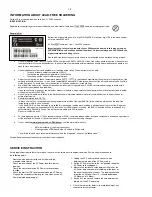
2) Press SYSTEM on the remote to exit the
system men
u and then DISC to exit progressiv
e
scan.
Sometimes a small amount of picture distor
tion
ma
y appear
. This is not a malfunction.
Clean the disc
.
TV has a colour system standard.
If the disc’
s or
D
VD system’
s colour system is different than
your
TV’
s colour system,
the picture ma
y be
distor
ted or colour
less.
Summary of Contents for MCD300
Page 13: ...3 1 3 1 SERVICE TEST PROGRAM ...
Page 15: ...SET WIRING DIAGRAM ONLY FOR MCD300 5 1 5 1 ...
Page 16: ...SET WIRING DIAGRAM ONLY FOR MCD305 5 2 5 2 ...
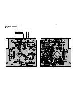
Page 18: ...LAYOUT DIAGRAM CPU BAORD 6 2 6 2 ...
Page 20: ...LAYOUT DIAGRAM TUNER BOARD ECO6 01 7 2 7 2 ...
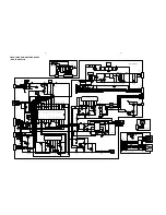
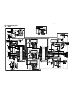
Page 21: ...CIRCUIT DIAGRAM AMPLIFIER BOARD ONLY FOR MCD300 8 1 2 1 8 1 ...
Page 23: ...LAYOUT DIAGRAM AMPLIFIER BOARD ONLY FOR MCD300 8 3 8 3 ...
Page 24: ...LAYOUT DIAGRAM AMPLIFIER BOARD ONLY FOR MCD305 8 4 8 4 ...


