background image

7A-3

7A-3

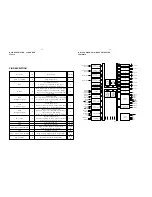
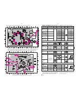
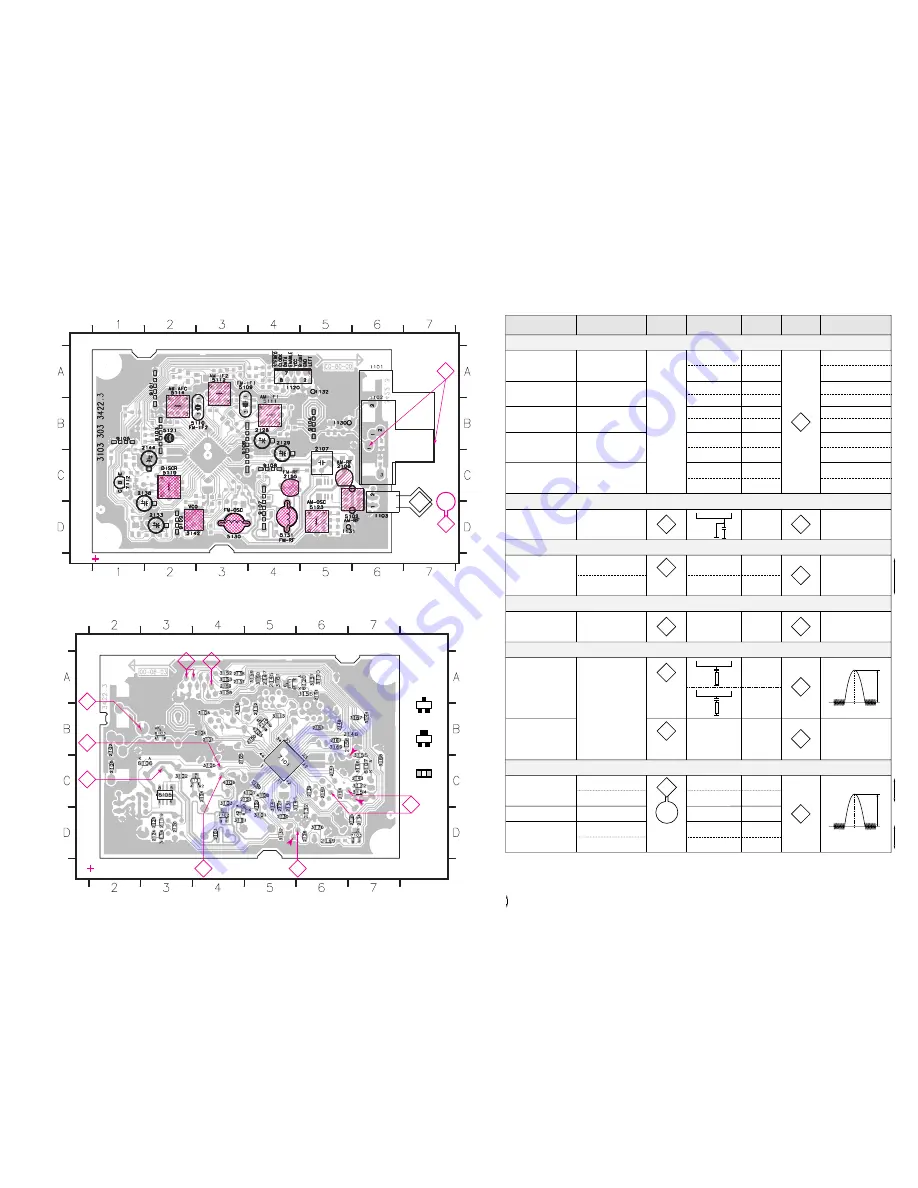
VARICAP  ALIGNMENT

FM RF

FM IF

VCO

AM IF

AM RF 

3)

108MHz

87.5MHz

(65.81MHz)

87.5MHz

(65.81MHz)

87.5MHz

(65.81MHz)

279kHz

153kHz

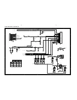
1602kHz

531kHz

5130

check

5122

check

5123

check

8V 

±

0.2V

4.3V 

±

0.5V

(1.2V 

±

0.5V)

8V 

±

0.2V

1.1V 

±

0.4V

8V 

±

0.2V

1.1V 

±

0.4V

1494kHz

558kHz

560kHz

5102

1500kHz

5103

198kHz

1494kHz

558kHz

560kHz

1500kHz

198kHz

2106

5102

2106

3142

152kHz 

±

1kHz 

1)

98MHz

5112

MAX

FM 
   87.5 - 108MHz
(65.81 - 74, 87.5 - 108MHz)

LW

  153 - 279kHz

MW

FM/MW/LW- version, 9kHz grid 

  531 - 1602kHz

1700kHz

530kHz

5123

check

8V 

±

0.2V

1.1V 

±

0.4V

1602kHz

531kHz

5123

check

6.9V 

±

0.2V

1.1V 

±

0.4V

108MHz

108MHz

2155

5131

MW

FM/AM-version, 10kHz grid

   530 - 1700kHz


FM

MW

LW

98MHz, 1mV

continuous wave

450kHz

connect pin 6 of

IC 7101 (AM Osc.)

with 3.3k

 to Vcc

Use Service Testprogram. By selecting the TUNER TEST test frequencies will be stored as preset frequencies automatically.

4

1

3

5

5

A

A

5119

FM

10.7MHz, 45mV

continuous wave

2

D

mod=1kHz

f=

±

22.5kHz

1)

 If sensitivity of frequency counter is too low adjust to max. channel separation

    (input signal: stereo left 90% + 9%, adjust output on right channel to minimum)

Repeat

ECO6, Sys + PA with frame aerial,  070799

TUNER ADJUSTMENT TABLE 

ECO6  FM/MW- and FM/MW/LW - versions with AM-frame aerial )  

f=

±

10kHz

V

RF

 = 0.5mV

C

see 
remark 2)

220R

100nF

36

IC 7101

220R

100nF

40

IC 7101

2141

shortcircuit
to block AFC

21

IC 7101

max.

symmetric

f

o

AM AFC

MW

C

continuous wave

V

RF

 = 2mV

5111

5114

2

±

 2 mV DC

±

 3 mV DC

MW 

4)

FM/MW/LW- and FM/MW-version
           ( 9kHz grid)

  531 - 1602kHz

B

f = 

±

30kHz

V

RF

 as low as

possible

max.

symmetric

f

o

MW

FM/AM-version, 10kHz grid

  530 - 1700kHz

3)

 For AM RF adjustments the original frame antenna has to be used !

2)

 RC network serves for damping the IF-filter while adjusting the other one.

4)

 MW has to be aligned before LW.

Waverange

Input frequency

Input

Tuned to

Adjust

Output

Scope/Voltmeter

FM 
   87.5 - 108MHz
(65.81 - 74, 87.5 - 108MHz)

FM/MW-version, 9kHz grid

   531 - 1602kHz

(as low as

possible)

ECO6 System non Cenelec stage .3, 120900

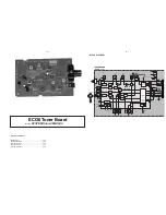
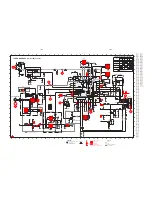
TUNER BOARD ECO6 

Systems non Cenelec /

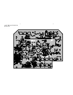
 componentside view

  1101  A6   
  1102  B6   
  1103  D6   

  1120  A4   
  1130  B5   
  1131  D5   

  1132  A5   
  2106  C5   
  2107  B5   

  2128  C4   
  2129  B4   
  2133  D2   

  2138  C2   
  2144  B2   
  2155  C4   

  3142  D2   
  5102  D6   
  5109  A3   

  5110  B3   
  5111  B4   
  5112  A3   

  5114  A2   
  5119  C2   
  5121  B2   

  5123  D5   
  5130  D3   
  5131  D4   

  7112  C1   
  9101  A2   
  9103  B2   

  9104  B5   
  9105  B1   
  9106  B3   

  9107  D4   
  9108  C4   
  9109  D2   

AM FRAME AERIAL

FM 75

B

A

TUNER BOARD ECO6 

Systems - non Cenelec /

 copperside view

  2101  B4
  2102  B1
  2103  D4   
  2104  B4
  2105  C1
  2112  B5

  2119  D3
  2120  D3   
  2124  D3   
  2125  D3   
  2126  D6   
  2127  C5   

  2130  D5   
  2131  C5   
  2132  D6   
  2134  D7   
  2135  D7   
  2136  A4   

  2137  A4   
  2139  C6   
  2140  C6   
  2141  C6   
  2143  C7   
  2145  A5   

  2146  B7   
  2147  A5   
  2148  B6   
  2149  D6   
  2150  B5   
  2152  C5   

  2153  C5   
  2154  C4   
  2159  C5   
  2161  A6   
  2163  B6   
  2164  C6   

  2165  C4   
  2166  B6   
  2167  B6   
  2169  A4   
  3101  D5   
  3102  C3   

  3103  C4   
  3104  B4   
  3105  C4   
  3113  B5
  3119  B5
  3132  D5   

  3134  D3   
  3141  C5   
  3143  D6   
  3144  B7   
  3145  C5   
  3146  C7   

  3152  A4   
  3153  A4   
  3154  C7   
  3155  C7   
  3156  A6   
  3157  A6   

  3158  A4   
  3159  A5   
  3160  A5   
  3161  A5   
  3167  B7   
  3168  C7   

  3169  B6   
  3170  A6   
  3172  C7   
  3176  D6   
  3181  D4   
  4103  B5   

  4106  C4   
  4107  C5   
  4108  C5   
  6103  B3   
  6105  C3   
  6106  C3   

  6107  C7   
  6120  A6   
  6130  D4   
  6131  C4   
  7101  C5   
  7102  D4   

  7103  D7   
  7111  A5   
  7119  B5

These assembly drawings show a summary of all possible versions.
For components used in a specific version see schematic diagram respectively partslist.

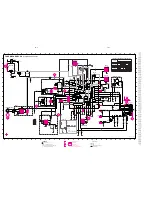
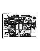
ECO6 Systems non CENELEC stage .3, 120900

41..

in schematic diagram)

(not all items shown

SMD jumper

E

B

C

A

K

1

2

7

8

4

D

A

C

1

2

5

3

Vdd

Vcc2

Vcc1

Summary of Contents for MCD510/14

Page 1: ... Wiring diagram 5 1 Display Board 6 Tuner Board ECO Non Cenelec 7A Tuner Board ECO Cenelec 7B Main Board 8 Cassette Board 9 Output Microphone Board 10 Power Board 11 Set Mechanical Exploded view parts list 12 Revision LIst 13 Copyright 2005 Philips Consumer Electronics B V Eindhoven The Netherlands All rights reserved No part of this publication may be reproduced stored in a retrieval system or tr...

Page 2: ...Surround RDS x News x Dolby Pro Logic DPL Incredible Surround Karaoke Features Voltage Selector ECO Power Standby LCD Display Off x ECO6 Tuner Board Systems Non Cenelec ECO6 Tuner Board Systems Cenelec VERSION VARIATIONS Type Versions MCD510 Features Board in used 22 x x x x x x x 21M x x x x x x 14 21 x x x x x x x x x x x x x x x ...

Page 3: ... sensitivity Aux in at 1kHz 500mV at 600 Ω Output sensitivity Headphone output at 32 kΩ 12mW 1dB Max vol COMPACT DISC Frequency response within 3dB 20Hz 20kHz Output level in Vrms 500mV Zout 100Ω Signal Noise ratio A weighted 65dBA Distortion at 1kHz 0 02 Channel unbalance at 1kHz 2dB Channel separation at 1kHz 30dB Emphasis 15 50 µS switched automatically by CD10 THD Noise 1kHz 0 5 Outband Attenu...

Page 4: ... To avoid atmospheric interference all AM measurements have to be carried out in a Faraday s cage Use a bandpass filter or at least a high pass filter with 250Hz to eliminate hum 50Hz 100Hz RF Generator e g PM5326 Ri 50Ω L R LEVEL METER e g Sennheiser UPM550 with FF filter S N and distortion meter e g Sound Technology ST1700B DUT CD Use Audio Signal Disc SBC429 4822 397 30184 replaces test disc 3 ...

Page 5: ...t Disc 4822 395 10216 ESD Equipment Anti static table mat large 1200x650x1 25mm 4822 466 10953 anti static table mat small 600x650x1 25mm 4822 466 10958 Anti static wristband 4822 395 10223 Connectorbox 1MΩ 4822 395 11307 Extension cable to connect wristband to conn box 4822 320 11305 Connecting cable to connect table mat to conn box 4822 320 11306 Earth cable to Connect product to mat or box 4822...

Page 6: ...n osservazione della più grande cauzione alla loro manipolazione Durante le riparazioni occorre quindi essere collegato allo stesso potenziale che quello della massa dell apparecchio tramite un braccialetto a resistenza Assicurarsi che i componenti e anche gli utensili con quali si lavora siano anche a questo potenziale Pour votre sécurité ces documents doivent être utilisés par des spécia listes ...

Page 7: ...es has to be purchased at external companies Special information for BGA ICs always use the 12nc recognizable soldering temperature profile of the specific BGA for de soldering always use the lead free temperature profile in case of doubt lead free BGA ICs will be delivered in so called dry packaging sealed pack including a silica gel pack to protect the IC against moisture After opening dependent...

Page 8: ...45 degrees from the listening position Notes To avoid magnetic interference do not position the front speakers too close to your TV set Allow adequate ventilation around the DVD System Connections Step 2 Connecting speakers Connect the speaker wires to the SPEAKERS terminals right speaker to R and left speaker to L coloured marked wire to and black unmarked wire to Fully insert the stripped portio...

Page 9: ...VIDEO OUT AUDIO IN S VIDEO IN VIDEO IN TV IN AUDIO IN S VIDEO IN VIDEO IN TV IN 2 1 Connections Using S Video In jack IMPORTANT If the picture is distorted check the Video Output setting Make sure it is set to S Video See Setting video preference LINE OUT DIGITAL OUT R L FM 75 FM MW ANTENNA SCART OUT VIDEO OUT S VIDEO OUT AUDIO IN S VIDEO IN VIDEO IN TV IN AUDIO IN S VIDEO IN VIDEO IN TV IN 2 1 1 ...

Page 10: ...udio visual device such as a TV VCR Laser Disc player or cassette deck Before starting operation press SOURCE on the front panel to select AUX or press AUX on the remote in order to activate the input source Connecting an active subwoofer B Connect the DVD micro system s SUBWOOFER OUT jack to the AUDIO INPUT jack on an active subwoofer not supplied SUB WOOFER OUT AUX CDR IN R LINE OUT DIGITAL OUT ...

Page 11: ...o open the tape compartment 0 2 to start or interrupt playback 9 for DVD VCD CD MP3 CD to stop playback or to clear a program for Tape to stop playback or recording VOLUME to increase or decrease the volume RECORD to start recording CLOCK SET RDS for Clock on the system only to set the clock function for tuner displays RDS information iR sensor infrared sensor for remote control OPEN CLOSE 0 to op...

Page 12: ...e only to enter or exit the disc contents menu Notes for remote control First select the source you wish to control by pressing one of the source select keys on the remote control DISC or TUNER for example Then select the desired function 2 w w for example Press and hold the button for more than two seconds w PREPARATIONS AND CONTROLS Preparations IMPORTANT Make sure to complete the preparation pr...

Page 13: ...Or set TV to channel 3 or 4 if you are using an RF modulator Language TV Shape TV System Video Out Video 4 3 LB 4 3 LB 4 3 PS 16 9 Auto S VIDEO Audio Rating 1 In the disc mode stop playback and press SYSTEM MENU 2 Press 22 33 5 4 on the remote control to toggle through the functions and select your preferential option Move to Video and press OK or 4 Move to one of the following and press OK or 33 ...

Page 14: ...r Disconnect the power plug from the jack and insert again Troubleshooting Problem Solution The language for the sound or subtitle cannot be changed when playing a DVD No image is output when a function is selected Sound cannot be heard or is of poor quality Poor radio reception Recording or playback cannot be made The tape deck door cannot open Left and right sound outputs are reversed The remote...

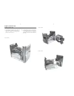
Page 15: ...ure 2 Lift up and out Push catches on two sides A Figure 3 1 Remove 2 screws B see Figure 3 from the bottom of the Cabinet Front Detaching the Front Panel assembly from the Bottom Rear assembly 2 Release the fixation of the Combi Board pos1102 1003 to Bracket Combi pos 155 by releasing the 2 catches C1 see Figure 7 and pulling the Combi Board outwards as shown in Figure 7A 3 Uncatch 2 catches C2 s...

Page 16: ...8 to remove the Tuner Board assembly 2 Loosen 5 screws L see Figure 8 to free the Main Board 3 Loosen 1 screw M see Figure 8 to free the Mains Socket Bracket 4 Loosen 1 scew N and 2 catches C6 see Figure 8 to free the Panel Rear by sliding it out towards the rear Note Tuner Board assembly and Mains Socket Bracket can also be removed together with the Panel Rear Figure 7 C D F E ...

Page 17: ...ner Board and or CD Module completely unless the fault is sus pected to be in that area This will not affect the performance of the rest of the set Note The flex cables are very fragile care should be taken not to damage them during repair After repair be very sure that the flex cables are inserted properly into the flex sockets before encasing otherwise faults may occurs ...

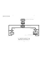
Page 18: ...oor switch is ignored CD door can be opened is software version eg D510 V0 10 SERVICE stands for Service mode Y Display shows version number of the µP software PLAY button pressed skip to Display shows all segments and flags for checking open circuits see figure 1 Figure 1 Display shows RESET Display shows SERVICE D510 VX XX N Show Software Version D510 VX XX ...

Page 19: ...C 230V Control singal MPEG BOARD MAIN BOARD POWER BOARD MICROPHONE BOARD FRONT PANEL BOARD MPEG BOARD MICROPHONE BOARD FRONT PANEL BOARD MAIN BOARD SFTY DVD ON TUNER ON OP 4558 MCU 12V 12V RF RCA JACK CLK DVD SEL DVD GND DOOR SW DTA DVD VGND VGND GND D5V MGND 21V PWR_ON ECHO LINE_MUTE SFTY AMP_MUTE 12V SDA DVD_PWR R_PWR INT RELAY GND CLK HD_DET RECITFIER BOARD SCART BOARD VFD BOARD VFD KEY BOARD V...

Page 20: ...121000 REC_R REC_R DVD LD DVD LD HEADER 5P P 2 5MM ST FFC TOP ENTRY 21P REC_L REC_L C C P N 3505 050102000 3106 120721000 3106 120721000 T T J8 12V 100MM 12V CP605 FFC TOP ENTRY 7P FFC TOP ENTRY 7P T T AGND 5PIN PLUG TO BOARD IN AGND F F R_DVD JUMPER UL1007 AWG 26 R_DVD F F L_DVD HOUSING L_DVD 12V 12V 3106 052411000 FFC TOP ENTRY 24P COAX PTICH 2 0MM COAX CN602 GND GND 3505 060102010 3101 20052101...

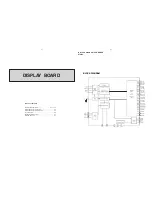
Page 21: ...ayout Bottom View 6 5 Circuit Diagram 6 6 Headphone Board Layout 6 7 Electrical Parts List 6 7 BLOCK DIAGRAM SG1 KS1 SG2 KS2 SG3 KS3 SG4 KS4 SG5 KS5 SG6 KS6 SG7 KS7 SG8 KS8 SG9 KS9 SG10 KS10 SG11 KS11 SG12 KS12 SG13 KS13 SG14 KS14 SG15 KS15 SG16 KS16 SG21 GR8 SG22 GR7 SG23 GR6 SG24 GR5 24 12 IC BLOCK DIAGRAM VFD DRIVER PT6315 ...

Page 22: ...9 VEE Pull Down Level 30 SG17 GR12 to SG24 GR5 O High Voltage Segment Grid Output Pins 31 to 38 GR4 to GR1 O High Voltage Grid Output Pins 39 to 42 16 bit timer event counter 00 TI000 TO00 P70 TI010 P71 Serial interface CSI1 SI1 P20 SO1 P21 SCK1 P22 Serial interface SIO3 SI3 P34 SO3 P35 SCK3 P36 RxD0 P23 TxD0 P24 ASCK0 P25 ANI0 P10 to ANI7 P17 UART0 Interrupt control 16 bit timer event counter 01 ...

Page 23: ...ress strobe AVREF Analog reference voltage AVSS Analog ground BUZ Buzzer clock IC Internally connected INTP0 to INTP3 External interrupt input P00 to P03 Port 0 P10 to P17 Port 1 P20 to P25 Port 2 P30 to P36 Port 3 P40 to P47 Port 4 P50 to P57 Port 5 P64 to P67 Port 6 P70 to P75 Port 7 P80 Port 8 IC PIN CONFIGURATION MICROCONTROLLER uPD780078 IC BLOCK DIAGRAM RDS RBDS DEMODULATOR SAA6581T 57 kHz 8...

Page 24: ...LAYOUT DIAGRAM DISPLAY BOARD TOP SIDE 6 4 6 4 ...

Page 25: ...6 5 6 5 LAYOUT DIAGRAM DISPLAY BOARD BOTTOM SIDE ...

Page 26: ...6 6 6 6 CIRCUIT DIAGRAM DISPLAY BOARD ...

Page 27: ...50 SW14 9940 000 03349 SWITCH TACT TSA 064301 250 SW2 9940 000 03349 SWITCH TACT TSA 064301 250 SW3 9940 000 03349 SWITCH TACT TSA 064301 250 SW4 9940 000 03349 SWITCH TACT TSA 064301 250 SW5 9940 000 03349 SWITCH TACT TSA 064301 250 SW6 9940 000 03349 SWITCH TACT TSA 064301 250 SW7 9940 000 03349 SWITCH TACT TSA 064301 250 SW8 9940 000 03349 SWITCH TACT TSA 064301 250 SW9 9940 000 03349 SWITCH TA...

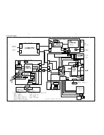
Page 28: ... 6 5 43 C D 450kHz 450kHz 450kHz 20 75kHz VStabA VStabB VStabB VStabA VStabB 10 7 MHz 10 7 MHz 35 9 Vdd Vcc1 7 23 VStabA VStabB 38 34 22 Vcc2 8 ECO6 Systems 140499 LF filter RDS MPX RDS MPX stereo clock data enable Version 1120 1 8 FM Frontend AM Frontend AM FRAME AERIAL B 1103 1101 1102 A FM MPX buffer ampl 5 Discriminator 10 7 MHz Vdd Vcc1 Vcc Vcc2 AM RF AM Osc FM Osc FM RF FM IF 1 FM IF 2 AM IF...

Page 29: ...1n 3134 22K 6105 2 HN1V02H 100n 2163 T141 7KL 1K 3144 5102 3157 100K T109 470R 3153 2130 22n 220R 3105 3142 100K 3167 120R 33p 2149 2K2 3145 1132 C PAD T103 T111 2164 470n T102 2140 15p 2139 2138 2u2 82p 2133 1u 3103 8K2 T120 4p7 2154 3156 1101USA YKD21 100K 2161 100n 5119 2119 10p T142 5123 11p 2106 3172 6106 BAS216 100n 2165 5K6 3154 3155 220R 330R 2124 33K 3176 22n WRITE EN 5114 7P MUTE P0 P1 P...

Page 30: ...riginal frame antenna has to be used 2 RC network serves for damping the IF filter while adjusting the other one 4 MW has to be aligned before LW Waverange Input frequency Input Tuned to Adjust Output Scope Voltmeter FM 87 5 108MHz 65 81 74 87 5 108MHz FM MW version 9kHz grid 531 1602kHz as low as possible ECO6 System non Cenelec stage 3 120900 TUNER BOARD ECO6 Systems non Cenelec componentside vi...

Page 31: ...10 63V RDS only RESISTORS 3101 4822 051 20333 33kΩ 5 0 1W 3102 4822 117 10837 100kΩ 1 0 1W 3103 4822 051 20822 8 2kΩ 5 0 1W 3104 4822 117 13577 330Ω 1 0 1W 3105 4822 117 11503 220Ω 5 0 1W 3132 4822 051 20479 47Ω 5 0 1W 3134 4822 051 20223 22kΩ 5 0 1W 3141 4822 117 11148 56kΩ 1 0 1W 3142 4822 100 12159 TRIMPOT 100kΩ RESISTORS 3143 4822 051 20223 22kΩ 5 0 1W RDS only 3144 4822 051 10102 1kΩ 2 0 25W ...

Page 32: ... B V Stab B V Stab A V Stab B 10 7 MHz 10 7 MHz 35 9 Vdd Vcc1 7 23 V Stab A V Stab B 38 34 22 Vcc2 8 ECO6 Systems Cenelec 140499 V Loop FM AM RF AM Osc FM IF 1 FM IF 2 LF filter MPX buffer ampl RDS MPX 5 RDS MPX stereo clock data enable Version 3 1120 AM IF 1 AM IF 2 AM AFC 1 8 AM Frontend 2 AM FRAME AERIAL B 1103 1101 1102 A FM AM FM Discriminator 10 7 MHz Vdd FM Vcc1 Vcc Vcc2 MW LW AM RF AM Osc ...

Page 33: ...4 22n USA 22n USA C PAD 1131 T141 2106 11p 20p_LW 0R 4104 0R 41xx 2165 100n 1130 C PAD 10K 3180 2150 100n BZX284 C11 6107 T102 2127 22n 2169 22n 100K 3170 1 I 3 O 2125 560p 5109 2 G 470R 3152 2108 100p 3125 10K 3153 470R 330R 3193 T103 120R 3167 100R 3195 7 8 33K 3176 8 5122 1 2 3 4 6 5123 1 2 3 4 6 7 5110 G 2 I 1 O 3 5115 1 2 3 4 6 7 8 2 3 4 6 7 8 5119 1 2135 100n 2163 LW 7104 BC337 40 2145 220p ...

Page 34: ...ce Testprogram By selecting the TUNER TEST test frequencies will be stored as preset frequencies automatically AM FRAME AERIAL FM 75Ω FM FRONTEND Birdy Filter ECO6 Sys Cenelec layout stage 8 200803 1101 B5 1102 B5 1103 C5 1110 B4 1120 A4 1130 A5 1131 C5 1132 A4 2106 B4 2107 B3 2128 A3 2129 B3 2133 C1 2138 B1 2144 B1 2162 A4 2191 B4 3142 C2 5102 C4 5103 C4 5109 B3 5110 A2 5111 A3 5112 A2 5114 A2 51...

Page 35: ...6W 3131 3198 021 38210 820Ω 5 0 06W 3132 4822 051 20479 47Ω 5 0 1W 3134 4822 051 20223 22kΩ 5 0 1W 3135 3198 021 31020 1kΩ 5 0 06W 3137 4822 051 20223 22kΩ 5 0 1W LW only 3141 4822 117 11148 56kΩ 1 0 1W 3142 4822 100 12159 TRIMPOT 100kΩ 3143 4822 051 20223 22kΩ 5 0 1W RDS only 3144 4822 051 10102 1kΩ 2 0 25W RDS only 3145 4822 117 11449 2 2kΩ 1 0 1W 3146 4822 051 20229 22Ω 5 0 1W 3150 4822 117 108...

Page 36: ...rical Parts List 8 5 BLOCK DIAGRAM 4 CHANNEL AUDIO AMPLIFIER TDA8947J TDA7468 INTERNAL BLOCK DIAGRAM VOLUME I RIGHT SUR SOURCE SUPPLY POWER SELECTOR TREBLE LEFT VOLUME II LOGIC LEFT REC IIC BUS BASS ALC BASS LEFT VOLUME I LEFT SUR TREBLE RIGHT VOLUME II RIGHT BASS RIGHT 17 14 15 9 20 1 13 28 3 26 4 25 5 24 6 23 8 21 2 7 22 12 TDA7468 16 10 19 11 18 27 ...

Page 37: ...LAYOUT DIAGRAM MAIN BOARD TOP SIDE 8 2 8 2 ...

Page 38: ...8 3 8 3 LAYOUT DIAGRAM MAIN BOARD BOTTOM SIDE ...

Page 39: ... 1K CA303 100uF16V CH3 220uF10V RA212 33K UA101 TDA7468D VS 1 MIC 2 L_IN1 RADIO 3 L_IN2 TAPE 4 L_IN3 AUX 5 L_IN4 DVD 6 MUX_L 7 L_IS 8 L_TRE 9 L_B_IN 10 L_B_O 11 L_OUT 12 DGND 13 SCL 14 SDA 15 ALC 16 R_OUT 17 R_B_O 18 R_B_IN 19 R_TRE 20 R_IS 21 R_MUX 22 R_IN4 23 R_IN3 24 R_IN2 25 R_IN1 26 CREF 27 AGND 28 RA131 22K RA108 2 2K RA304 33K CS9 100uF16V RH4 220R CA124 10uF16V RF1 100R QA204 DTA114YKA RA4...

Page 40: ... ZENER DIODE 9 1V JK601 9940 000 02174 SPK TERMINAL TC08 043 01 JK603 9940 000 03315 JACK RCA 405A 04 W R JK604 9940 000 03313 JACK RCA 1P D8 4MM BLACK JK605 9940 000 03314 JACK RCA 1P D8 4MM ORANGE LA1 9940 000 03589 IND 3A1868N 8µH 20 0 06Ω LA2 9940 000 03589 IND 3A1868N 8µH 20 0 06Ω LA3 9940 000 03589 IND 3A1868N 8µH 20 0 06Ω LA4 9940 000 03589 IND 3A1868N 8µH 20 0 06Ω LS301 9940 000 03308 POWE...

Page 41: ...el Circuit Diagram and Printed Circuit Board drawings are published for orientation only In case of defects please replace the entire board and mechanic The Cassette Board can be ordered with codenumber 9940 000 03339 The Cassette Deck can be ordered with codenumber 9940 000 03317 ...

Page 42: ...LAYOUT DIAGRAM CASS BOARD TOP SIDE 9 2 9 2 LAYOUT DIAGRAM CASS BOARD BOTTOM SIDE ...

Page 43: ...4 2 2uF50V R833 18K C822 220pF Q810 BC847C C804 1uF50V R814 3 3K C818 47uF16V C840 0 0047 R820 1K R822 22K C810 0 018 R823 22K R844 22k C839 0 022M Q803 BC847C R842 10K C811 2 2uF50V M W991S 390 1 3 2 4 5 6 7 8 Q801 BC847C R859 18K R825 27K C842 47uF16V R808 5 6K R819 10K Q806 BC847C Q802 BC847C R817 47K C813 220uF16V D801 1N4148 R841 33K R826 27K R840 4 7K C835 220pF R818 10K CN801 7PIN HOUSING 2...

Page 44: ... OUTPUT BOARD TOP SIDE LAYOUT DIAGRAM OUTPUT BOARD BOTTOM SIDE TABLE OF CONTENTS Output Board Layout Top View 10 1 Output Board Layout Bottom View 10 1 Output Board Circuit Diagram 10 2 Microphone Board Circuit Diagram 10 3 Electrical Parts List 10 4 ...

Page 45: ...9 1 2 3 C131 100P R151 220 T53 1 ZD1 BAV99 1 2 3 R162 FB 600R 100Mhz JR1 RCA 108 PB 1 3 C136 0 1U 1 JR2 DSW 21 4 3 2 1 6 5 T54 1 C142 47P 1 R153 1K ZD4 BAV99 1 2 3 R152 820 R156 0R FB33 FB C138 0 1uF R154 10K FB21 FB C137 0 1U 1 C113 0 1U 1 ZD6 BAV99 1 2 3 R163 470R ZD9 BZX79 C3V3 1 2 L13 4 7uH C140 0 1U 1 R150 220 ZD3 BAV99 1 2 3 C130 100P T50 1 T52 1 FB29 0 R159 0 T49 1 FB34 FB 600R 100MHz SC1 S...

Page 46: ...10 3 10 3 CIRCUIT DIAGRAM MICROPHONE BOARD ONLY FOR 21M ...

Page 47: ...rmal service parts ELECTRICAL PARTSLIST OUTPUT BOARD JR1 9940 000 03336 JACK RCA 1P D8 4MM JR2 9940 000 03337 JACK DSW 12 S VIDEO 6PIN JR3 994000003595 JACK RCA D8 4MM R 21 21M JR4 994000003596 JACK RCA D8 4MM B 21 21M JR5 994000003597 JACK RCA D8 4MM G 21 21M Q2 9940 000 03333 TRANSISTOR BT3904 14 22 Q5 9940 000 03333 TRANSISTOR BT3904 14 22 SC1 9940 000 03338 JACK SCART CS 109 14 22 ZD1 9940 000...

Page 48: ...11 1 11 1 POWER BOARD TABLE OF CONTENTS Power Board Layout Diagram 11 2 Power Board Circuit Diagram 11 3 AC Socket Board Layout Diagram 11 4 Electrical Parts List 11 4 ...

Page 49: ...11 2 11 2 LAYOUT DIAGRAM POWER BOARD ...

Page 50: ...1 2 D305 1N4001 F302 T4A 120V T301 EI76 4 9 10 11 12 3 2 13 16 14 T302 EI28 1 3 2 4 5 AC POWER CORD L301 3mH 2 5A 1 3 2 4 C305 0 02uF275V RL301 DC9V ME 7 009HL 4 3 1 2 SW301 AC SWITCH D301 1N4001 D302 1N4001 D304 1N4001 D303 1N4001 C302 0 02 C303 0 02 CON 1 2 CON 1 2 C301 0 02 C304 0 02 F301 T2AL 230V CN301 10PIN 2 5mm SOCKET 1 2 3 4 5 6 7 8 9 10 C307 470uF16V ...

Page 51: ... FS305 9940 000 03592 FUSE 2 5A 250V 21 21M L301 9940 000 03319 LINE FILTER 330UH 32MR 3A RL301 9940 000 03321 RELAY ME 7 009 9V 10A T301 9940 000 03323 TRASFO EI76X50 230V 22 14 T301 9940 000 03594 TRASFO EI 76x40 AC120 230V 21 21M T302 9940 000 03322 TRANSFORMER EI28 230V 22 14 T302 9940 000 03593 TRASFO EI28 AC120 230V 21 21M 9940 000 03327 AC POWER SOCKET 2P 2 5A 250V Note Only these parts men...

Page 52: ...12 1 12 1 01 02 03 04 06 07 08 09 11 12 13 14 15 16 18 19 17 21 22 23 24 27 28 29 31 32 33 33 34 36 39 35 37 38 26 SET MECHANICAL EXPLODED VIEW ...

Page 53: ...6 TOP BUTTON COVER 19 9940 000 03614 BRACKET TOP BUTTON 21 9940 000 01422 CD DOOR SWITCH 22 9940 000 03358 DOOR CD 23 9940 000 03615 SPRING CD DOOR EJECT 24 9940 000 03359 TRAY CD 26 9940 000 03356 PANEL LEFT 27 9940 000 03331 DVD MECHANISM KHM 310AHC 28 9940 000 03361 PANEL TOP 22 14 28 9940 000 03608 PANEL TOP 21M 21 29 9940 000 03611 MIC KNOB 21M 21 31 9940 000 03362 CABINET REAR 22 14 31 9940 ...

Page 54: ...ual 3141 785 30611 Add new version MCD510 14 and MCD510 21 The following have been updated 1 P1 2 Version Variations 2 P1 3 Specifications 3 P6 7 Electrical Partslist P8 5 Electrical Partslist P10 4 Electrical Partslist P11 4 Electrical Partslist P12 2 Mechanical Accessories Partslist ...

Reviews: