1-9
CONNECTIONS AND CONTROLS
Connections
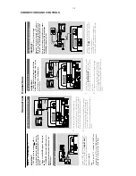
Step 4:
Connecting
TV
IMPOR
T
ANT!
–Y
ou onl
y need to mak
e
one
video
connection fr
om the follo
wing options,
depending on the ca
pabilities of y
our
TV
system.
–
Connect the D
VD system dir
ectl
y to
the TV
.
–A
SCAR
T connection will let y
ou use
featur
es both
Audio and
Video on the
D
VD Pla
y
er
.
Using SCAR
T jack
SCART OUT
VIDEO OUT
S-VIDEO OUT
AUDIO
IN
S-VIDEO
IN
VIDEO IN
TV IN
AUDIO
IN
S-VIDEO
IN
VIDEO IN
TV IN
1
Use the SC
AR
T
cable (b
lack) to connect the
D
VD Pla
yer’
s SC
AR
T jack (
SCAR
T OUT
) to
the cor
responding Scar
t input jacks on the
TV
(cable not supplied)
.
Note:
–
Ensur
e that the
“TV”
indication on SC
AR
T cable
is connected to the
TV set and
“D
VD”
indication on
SC
AR
T cable is connected to the D
VD Play
er
.
Using Composite
Video jacks (CVBS)
1
Use the composite video cab
le (y
ello
w) to
connect the D
VD Pla
yer’
s CVBS (VIDEO OUT)
jack to the video input jack (or labeled as
A/V In,
Video In,
Composite or Baseband) on the
TV
.
2
To
hear the sound of this D
VD Pla
yer through
your
TV
, use the audio cab
les (white/red) to
connect LINE OUT (L/R) jacks of the D
VD
Pla
yer to the cor
responding
A
UDIO IN jacks on
the TV
.
LINE OUT
DIGITAL
OUT
RL
FM 75
!&
FM/MW ANTENNA
SCART OUT
VIDEO OUT
S-VIDEO OUT
AUDIO
IN
S-VI
DEO IN
VI
DEO IN
TV IN
AUDIO
IN
S-VIDEO
IN
VIDEO IN
TV IN
2
1
Connections
Using S-Video In jack
IMPOR
T
ANT!
–
If the pictur
e is distor
ted,
check the
Video Output setting.
Mak
e sur
e it is set
to
‘S-Video’.
(See Setting video
pr
ef
er
ence).
LINE OUT
DIGITAL
OUT
RL
FM 75
!&
FM/MW ANTENNA
SCART OUT
VIDEO OUT
S-VIDEO OUT
AUDIO
IN
S-VID
EO
IN
VIDEO
IN
TV IN
AUDIO
IN
S-VIDEO
IN
VIDEO IN
TV IN
2
1
1
U
se the S-Video cab
le (not supplied) to connect
the system’
s
S-VIDEO OUT
jack to the S-
Video input jack (or labeled as
Y/C or S-VHS) on
the TV
set.
2
To
hear the sound of this D
VD Pla
yer through
your
TV
, use the audio cab
les (white/red) to
connect LINE OUT (L/R) jacks of the D
VD
Pla
yer to the cor
responding
A
UDIO IN jacks on
the TV
.
Using an accessor
y RF modulator
IMPOR
T
ANT!
–
If y
our
TV set onl
y has a single
Antenna In jack (or labeled as 75 ohm or
RF In),
y
ou will need a RF modulator in
or
der to view the D
VD pla
yback via
TV
.
See y
our electr
onics r
etailer or contact
Philips f
or details on RF modulator
a
vailability and operations.
SCART OUT
VIDEO OUT
S-VIDEO OUT
AUDIO IN
R L
VIDEO
IN
TO TV
ANT IN
CH3 CH4
2
1
RF coaxial cable to
TV
Back of RF Modulator
(example only)
Antenna or
Cable TV
signal
Use the composite cab
le (y
ello
w) to connect
the system’
s
CVBS
jack to the video input jack
on the RF modulator
.
Use the RF coaxial cab
le (not supplied) to
connect the RF modulator to y
our
TV’
s RF jack.
Summary of Contents for MCD510/14
Page 24: ...LAYOUT DIAGRAM DISPLAY BOARD TOP SIDE 6 4 6 4 ...
Page 25: ...6 5 6 5 LAYOUT DIAGRAM DISPLAY BOARD BOTTOM SIDE ...
Page 26: ...6 6 6 6 CIRCUIT DIAGRAM DISPLAY BOARD ...
Page 37: ...LAYOUT DIAGRAM MAIN BOARD TOP SIDE 8 2 8 2 ...
Page 38: ...8 3 8 3 LAYOUT DIAGRAM MAIN BOARD BOTTOM SIDE ...
Page 42: ...LAYOUT DIAGRAM CASS BOARD TOP SIDE 9 2 9 2 LAYOUT DIAGRAM CASS BOARD BOTTOM SIDE ...
Page 46: ...10 3 10 3 CIRCUIT DIAGRAM MICROPHONE BOARD ONLY FOR 21M ...


