background image

Version 1.1

MCD759

©

 3141 785 31291

DVD Micro theatre

all versions 

Published by LX 0705  Service Audio    Subject to modification

© 

Copyright 2006 Philips Consumer Electronics B.V. Eindhoven, The Netherlands

All rights reserved. No part of this publication may be reproduced, stored in a retrieval
system or transmitted, in any form or by any means, electronic, mechanical, photocopying,
or otherwise without the prior permission of Philips.

Handling chip components  ...........................................................1-1
Leadfree and safety information ....................................................1-2

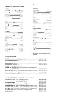
Technical specification ...................................................................2-1
Service tools  .................................................................................2-1
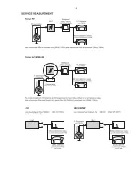
Service measurement setup ..........................................................2-2

Connections and controls ......................................................3-1...3-4
Dismantling instructions ........................................................4-1...4-2

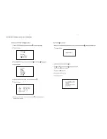
Software version check and upgrading .........................................5-1

Block diagram ................................................................................6-1
Wiring diagram  .............................................................................6-2

VFD Board 
 circuit 

diagram 

..........................................................................7-1 

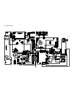
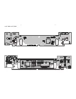
     layout diagram ..........................................................................7-2

Tuner Board
 circuit 

diagram 

..........................................................................8-1 

     layout diagram ..........................................................................8-2
   

 CPU Board
     circuit diagram ..........................................................................9-1 
     layout diagram  .........................................................................9-2

AMP Board & Power Board
 circuit 

diagram. 

.......................................................................10-1

 layout 

diagram 

..............................................................10-2...10-4

Woofer AMP Board
 circuit 

diagram. 

....................................................................... 11-1

 layout 

diagram 

.............................................................. 11-2...11-3

DVD MPEG Board
 circuit 

diagram. 

.............................................................12-1...12-4

 layout 

diagram 

........................................................................12-5

Exploded view diagram ...............................................................13-1
Mechanical partslist .....................................................................13-2

Electrical partslist...............................................................14-1...14-3
Revision list .................................................................................15-1

TABLE OF CONTENTS

Summary of Contents for MCD759

Page 1: ... 1 2 Technical specification 2 1 Service tools 2 1 Service measurement setup 2 2 Connections and controls 3 1 3 4 Dismantling instructions 4 1 4 2 Software version check and upgrading 5 1 Block diagram 6 1 Wiring diagram 6 2 VFD Board circuit diagram 7 1 layout diagram 7 2 Tuner Board circuit diagram 8 1 layout diagram 8 2 CPU Board circuit diagram 9 1 layout diagram 9 2 AMP Board Power Board circ...

Page 2: ...1 1 ...

Page 3: ...1 2 ...

Page 4: ...2 1 TECHNICAL SPECIFICATIONS ...

Page 5: ...2 2 ...

Page 6: ...3 1 CONNECTION AND CONTROLS ...

Page 7: ...3 2 CONNECTION AND CONTROLS gdci heZV Zg ...

Page 8: ...3 3 CONNECTION AND CONTROLS ...

Page 9: ...CONNECTION AND CONTROLS 3 4 ...

Page 10: ...M3x8 3pcs C remove screws M3x8 4pcs and T3x4 2pcs E1 E2 E2 E1 M2 5x5 E2 M2 6x8 D Remove Back Panel D remove screws T3x4 5pcs and M3x10 5pcs and T3x8 1pc E Remove Top Cover G Remove DVD Rom and then remove DVD Decoder Card Assy I Remove VFD board assy H Remove Slid Plank I Remove Side metal Plate DISASSEMBLY DIAGRAM DVD PART ...

Page 11: ... 6pcs and T3x10 4pcs C remove screws T3x4 5pcs D Remove Back Panel D remove screws T3x4 4pcs and T3x8 2pcs and M3x10 6pcs E Remove Top Cover F Remove AMP Board Assy E1 E2 E2 E1 M2 5x5 E2 M2 6x8 H Remove AMP Front board assy G Remove ALC Volume board assy I Remove Side metal Plate DISASSEMBLY DIAGRAM AMP PART ...

Page 12: ...5 1 5 1 SOFTWARE VERSION CHECK AND UPGRADING ...

Page 13: ...SET BLOCK DIAGRAM 6 1 6 1 ...

Page 14: ...6 2 6 2 SET WIRING DIAGRAM ...

Page 15: ...7 1 7 1 CIRCUIT DIAGRAM VFD BOARD ...

Page 16: ...7 2 7 2 LAYOUT DIAGRAM VFD BOARD ...

Page 17: ... 8 1 CIRCUIT DIAGARM TUENR BOARD 8 1 ...

Page 18: ...LAYOUT DIAGARM TUNER BOARD 8 2 8 2 ...

Page 19: ...K R52 20K C33 222M C37 10uF 16V C41 222M C60 100uF 16V C61 104P R54 47 C57 223 M C51 104 C50 104 R68 4 7k R69 100 C69 300 SDA SCL C40 4 7uF 50V C34 4 7uF 50V C38 4 7uF 50V C36 4 7uF 50V C39 4 7uF 50V C35 4 7uF 50V MPX A5V ST MO OPEN SW CLOSE SW M CLOSE M OPEN DVD SW ST MO CPU5V R65 10K R66 10K CPU5V R98 2 2K R97 2 2K R93 1K R94 1K Q7 8050 Q8 8050 1 2 3 4 5 CN12 5P 2 0 Q6 8550 Q5 8550 OPEN SW CLOSE...

Page 20: ...LAYOUT DIAGRAM CPU BOARD 9 2 9 2 ...

Page 21: ...0K C2059 104 C2058 100 C2054 100P C2051 104 C2052 102 C2053 470 C2056 100P C2011 33pf C2057 100P DZ201 5 6V XT201 700K XT202 600K R261 22 CLOCK FERQ HOP CLOCK CLOCK 1 2 3 CN206 3P 2 0 1 2 3 4 5 6 7 8 9 10 11 12 CN202 12P 2 0 FERQ HOP R268 1 5K C2062 100UF 16V C2061 104 DZ204 5 6V Vcc PD1 300KHZ 350KHZ 䆩 㑺 C201 220P C204 220P CEN IN C208 224 C207 224 SGND L217 10uh C213 104 F203 H1 5A 125V R208 330...

Page 22: ...LAYOUT DIAGRAM POWER BOARD 10 2 10 2 ...

Page 23: ...LAYOUT DIAGRAM AMP BOARD 10 3 10 3 ...

Page 24: ...LAYOUT DIAGRAM AMP BOARD 10 4 10 4 ...

Page 25: ...212 102 C2035 102 C2049 102 C2050 102 R234 10 R241 10 C234 220P C237 220P C2019 220P C2022 220P Vddp2 Vssp2 Vssp2 Vddp2 C2016 470uf 35v C2013 470uf 35v C228 22UF 100V C219 104 C225 104 R252 10 R247 10 Vcc C2027 47uf 35v C222 47uf 35v Vssp2 L211 JRH0349 L206 JRH0349 VSSA2 1 VDDA2 3 VSSD 24 STABL 18 PROT 13 SUB VSSD 19 VDDP2 23 VSSP2 20 BOOT2 22 OUT2 21 OUT1 16 BOOT1 15 VSSP1 17 VDDP1 14 MODE 6 OSC ...

Page 26: ...11 2 11 2 LAYOUT DIAGRAM WOOFER AMP BOARD ...

Page 27: ...11 3 11 3 LAYOUT DIAGRAM WOOFER AMP BOARD ...

Page 28: ... ESD NC D15 ESD NC D6 ESD NC R153 15k L45 FB U16 MT1392E HDMI TX PROCESSOR SPQFP80 SMD 1 2 3 4 5 6 7 8 9 10 11 12 13 14 15 16 17 18 19 20 21 22 23 25 24 26 27 28 29 30 31 32 33 34 35 36 37 38 39 40 41 42 43 44 45 46 47 48 49 50 51 52 53 54 55 56 57 58 59 60 61 62 63 64 65 66 67 68 69 70 71 72 73 74 75 76 77 78 79 80 DVSS C0 C1 C2 C3 C4 C5 C6 C7 DVDD33 VCK DVSS Y0 Y1 Y2 Y3 Y4 Y5 Y6 Y7 SSCK SSD DVDD...

Page 29: ...85 75 DIP 1 2W L25 FB R100 150 C65 47pF P1 AV3 8 4 13D 2 3 1 4 5 R97 75 DIP 1 2W C62 47pF C71 47pF C55 47pF C56 47pF R103 5 1k mk3 C77 47pF R206 100k Q22 8550 2 1 3 R110 5 1k Q17 8550 2 1 3 R99 75 DIP 1 2W R200 100K Q16 3906 2 1 3 CB53 0 1uF U11A 4558 3 2 1 8 4 mk2 CE23 220uF 16V L26 1 8uH C63 47pF C64 47pF Q12 8550 2 1 3 C79 150pF C60 27pF L21 1 8uH R112 75 DIP 1 2W CE26 100uF 16v C54 47pF CE33 4...

Page 30: ... 142 140 139 138 137 136 134 135 133 132 131 130 249 255 24 254 231 230 238 237 248 247 236 251 246 243 241 242 240 239 234 235 232 224 225 222 221 220 219 226 218 217 215 213 214 204 211 210 209 208 212 207 206 205 203 202 201 200 199 198 197 196 195 194 193 233 44 47 48 49 50 51 88 89 216 223 228 229 227 DVDA CRTPLP DVDB DVDC DVDD AGND OSP OSN DVDRFIP DVDRFIN MA MB MC MD SA SB SC SD CDFON CDFOP ...

Page 31: ... 0 022uF D21 1N4002 1 2 R49 15k CE8 100uF 16V CB12 0 1uF C7 330pF R39 20k U5 ACT4060 1 2 3 4 5 6 7 8 BS VIN VSW GND FB COMP EN SYNC R47 10k U4 ACT4060 1 2 3 4 5 6 7 8 BS VIN VSW GND FB COMP EN SYNC R31 1 0805 R30 1 0805 R2 10k R42 27K CE4 220uF 16V PT220 16V R37 20k R29 18k J1 PH 6A 1 2 3 4 5 6 L6 FB R11 0 L7 100uH_1 7A J4 TJC3 4A 1 2 3 R6 680k CB10 0 1uF CB4 0 1uF R46 300k L8 100uH_1 7A C15 0 1uF...

Page 32: ...LAYOUT DIAGRAM DVD MPEG BOARD MPEG is not repaired diagram for referrence only 12 5 12 5 ...

Page 33: ... 308 309 311 312 313 314 302 SCREW LIST M2 5x5 M2 5x8 M2 5x10 M3x8 M3x10 TP2 5x4 TP2 5x10 T3 x4 T3 x8 T3 x10 1 2 3 4 5 6 7 8 9 0 6 8x 5 4x 3 2x 2 8x 2 6x 2 6x 2 6x 2 9x 1 4x 8 2x 8 5x 8 2x 4 4x 8 2x 4 4x 8 2x 7 4x 0 4x 8 5x 8 4x 5 5x 5 6x 9 1x 9 2x 0 4x 5 11x 6 8x 2 9x 1 4x 415 403 431 432 DVD PART AMP PART EXPLODED VIEW DIAGRAM ...

Page 34: ...313 996510000470 AMP TOP COVER 314 996510000471 AMP REAR CABINET 316 996510000255 RUBBER FOOT B 317 996510000472 AMP BOTTOM HIPS 994000004884 AC SOCKET 1A 250V Note Only these parts mentioned in the list are normal service parts MECHANICAL PARTSLIST DVD PART 401 996510000253 DVD DISPLAY LENS 402 996500038468 DVD DOOR BRACKET 403 996510000242 DVD CABINET FRONT ABS 404 996510000252 DVD STANDBY BUTTO...

Page 35: ... 996510000228 RCA SOCKET 2p AV2 8 4 13 RD WH 996510000236 TUNER BOARD PCB ASS Y EC06 04 996510000224 CPU PCB ASS Y MCD759 996510000229 DISPLAY PCB ASS Y MCD759 DIODES LED1103 994000004947 LED DIODE D3 3B4SCB01 BLUE LED1104 994000004947 LED DIODE D3 3B4SCB01 BLUE LED1200 994000004947 LED DIODE D3 3B4SCB01 BLUE LED1100 994000004947 LED DIODE D3 3B4SCB01 BLUE LED1101 994000004947 LED DIODE D3 3B4SCB0...

Page 36: ...0 220V m 996510000264 AMP PCB ASS Y 2 MCD759 DIODES LED1001 996510000260 WHITE LED DIODE 3R41W71W EB LED1103 994000004947 LED DIODE D3 3B4SCB01 BLUE LED1104 994000004947 LED DIODE D3 3B4SCB01 BLUE LED1200 994000004947 LED DIODE D3 3B4SCB01 BLUE LED1100 994000004947 LED DIODE D3 3B4SCB01 BLUE LED1101 994000004947 LED DIODE D3 3B4SCB01 BLUE LED1201 994000004947 LED DIODE D3 3B4SCB01 BLUE IC TRANSIST...

Page 37: ... Q207 996500042558 MOSFET BUK7509 55A F201 994000004872 FUSE F6 3AL250V 50F F202 994000004872 FUSE F6 3AL250V 50F F203 994000004872 FUSE F1 5A 125V IC205 996510000463 CHIP IC 74HCU04D JACK302 996510000467 POWER SOCKET DC 101A EP JACK301 996510000467 POWER SOCKET DC 101A EP JACK201 994000004943 S SOCKET DS 106 IC206 996510000267 IC HEF4013T CHIP IC202 994000002526 IC 7812 IC203 996510000464 CHIP IC...

Page 38: ...VISION LIST Version 1 0 3141 785 31290 Initial Release Version 1 1 3141 785 31291 New version MCD759 93 is introduced Pages 13 2 Mechanical parts list adapted Pages 14 1 and 14 3 Electrical parts list adapted ...

Reviews: