DVD Micro System
MCDB710
TABLE OF CONTENTS
3141 785 32680
DB 0816
2008
Location of PCBS ............................................................ 1-1
Specifications ................................................................. 1-2
Measurement Setup ....................................................... 1-3
Service Aids, Safety Instruction, etc. .............................. 1-4
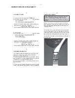
Instructions On CD Playability .............................. 1-5 to 1-6
Software Version Check & Upgrade
...............................2-1
Malfuction Check Chart .................................................. 2-2
Headphone& Volume Board .............................................8-1
Lamp,USB Lamp&USB Board ..........................................9-1
Decoder Board ...................................................................10
Power Board .....................................................................11
Disassembly Diagram
.................................................. 3-1
Block Diagram ................................................................. 4-1
Wiring Diagram................................................................. 4-2
Key-press Board .............................................................
5
Circuit diagram ........................................................... 5-1
Layout diagram ........................................................... 5-2
DAB VFD Board ..............................................................
6
Circuit diagram ........................................................... 6-1
Layout diagram ........................................................... 6-2
Data Transfer Board .......................................................
7
Circuit diagram ........................................................... 7-1
Layout diagram ........................................................... 7-2
Circuit diagram ...............................................11-1 to11-4
Layout diagram ......................................................... 11-5
Circuit diagram ..............................................10-1 to 10-7
Layout diagram ..............................................10-8 to 10-9
Explode View ................................................................. 12
Factory Partlist ................................................................. 14
Service Partlist ................................................................. 13
Summary of Contents for MCDB710
Page 9: ...2 2 Malfunction follow check chart ...
Page 11: ... ORFN LDJUDP ...
Page 12: ... LULQJ GLDJUDP ...
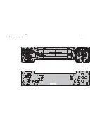
Page 14: ... H 3UHVV D RXW GLDJUDP ...
Page 16: ... 9 RDUG D RXW GLDJUDP ...
Page 18: ... DWD 7UDQVIHU RDUG D RXW GLDJUDP ...
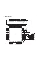
Page 28: ...10 8 10 8 Decoder Board Layout diagram Top ...
Page 29: ...10 9 10 9 Decoder Board Layout diagram Bottom ...
Page 30: ... 3RZHU RDUG LUFXLW GLDJUDP ...
Page 31: ... 3RZHU RDUG LUFXLW GLDJUDP ...
Page 32: ... 3RZHU RDUG LUFXLW JLDJUDP ...
Page 33: ...3RZHU RDUG LUFXLW GLDJUDP ...
Page 34: ... 3RZHU RDUG D RXW GLDJUDP ...
Page 35: ...Explode View 12 1 12 1 ...


