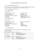
General requirement:
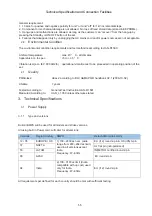
1. 10 arcs for positive and negative polarity for unit “on” and “off” for 1kV incremental steps.
2. Component or mechanical damage is not allowed. No loss of fixed stored data (stored in EEPROMs).
3. Hang-ups and malfunctions are allowed, as long as the customer can “recover” from the hang-up by
pressing the Standby or ON/OFF button of the set.
4. Failures that disappear only by unplugging the AC mains cord and/or power sources are not acceptable.
2.6
Environmental Condition
The environmental condition requirements and test method is according to UAN-D1590.
Ambient temperature
: max. 40 ° C - all climates
Apparatus acc. to spec.
: +5 to + 35 ° C
Vibration test (acc. IEC 60 068/2/6) : operational vibration test to be proceeded in operating position of the
set.
2.7
Quality
PQR-class: class 2 according to BLC A&MA PQR handbook V2.1 (2006-10-02)
Lifetime: 7 years
Tested According to: General Test Instruction UAN-D 1591
Measured According to: UAN_L 1059 unless otherwise stated
Technical Specification and Connection Facilities
1-5
3. Technical Specifications
3.1
Power Supply
3.1.1 Type
and
versions
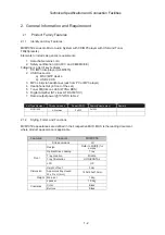
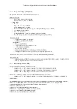
Build-inSMPS will be used for all models and stroke versions.
All using built in Power cord, will cater for all versions:
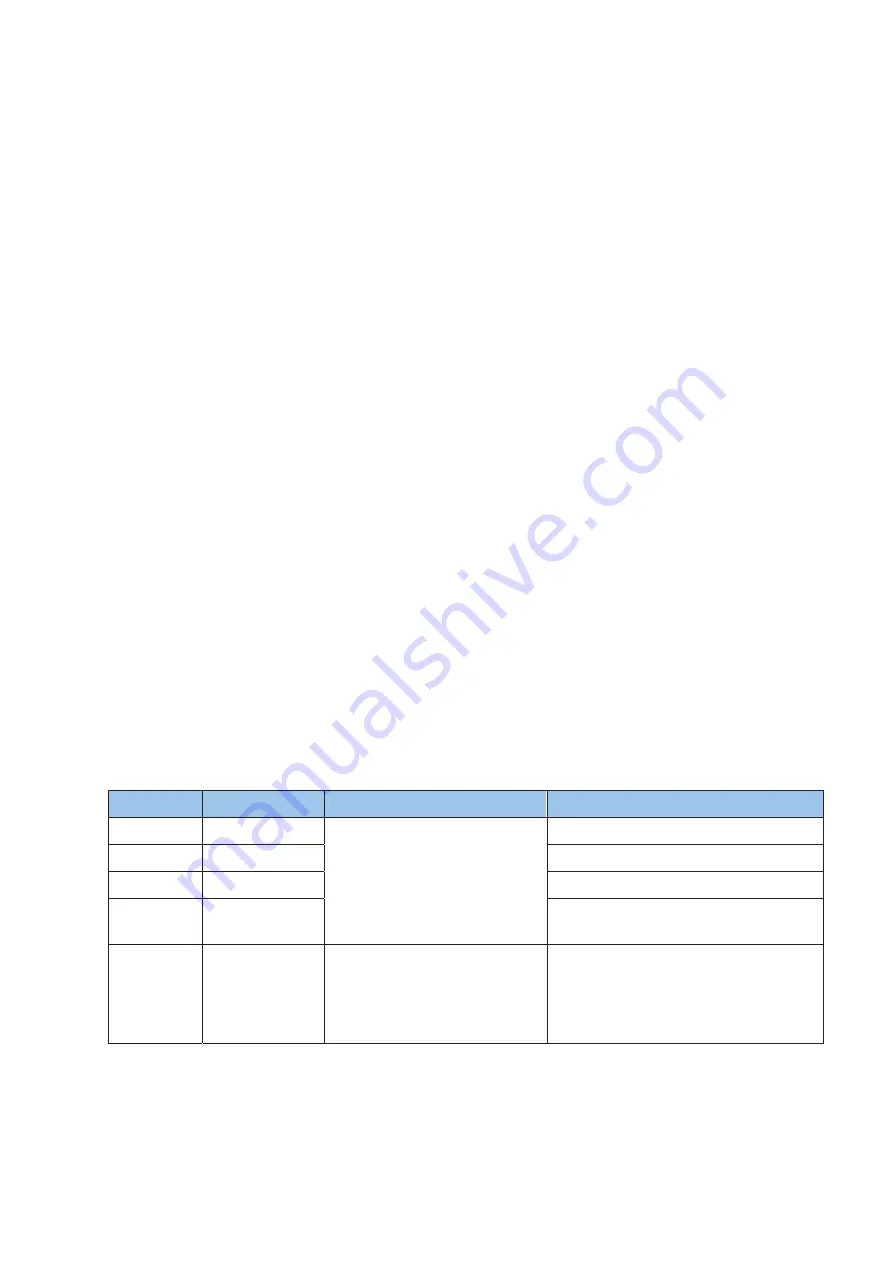
Versions
Region/Country SMPS
Detachable mains cords
12 / 05
EUROPE / UK
1) 100 ~240Vac nom. (wide
range from 90V~264Vac limit)
used in all versions except
India.
Frequency: 47~63Hz.
EU (/12) round 2-pin & UK (/05) 3-pin
37 NAFTA
UL flat pin (non-polarized)
n
i
p
-
2
d
n
u
o
r
d
e
i
f
i
t
r
e
c
O
R
T
E
M
N
I
M
A
T
A
L
5
5
n
i
p
-
2
d
n
u
o
r
U
E
C
A
P
A
8
9
94 India
2) 100 ~310Vac limit (India
compatible with up cost) used
only for India.
Frequency: 47~63Hz.
EU (/12) round 2-pin
All requirements per defined for each country should be met with sufficient testing.
Summary of Contents for MCM1050/12/93
Page 22: ...8 2 Fig D3 Fig D5 Fig D4 Cabinet Disassembly Instructions Fig D6 A02 A03 A04 A02 ...
Page 28: ...Display Board Layout Diagram 12 2 12 2 ...
Page 30: ...Power Board Layout Diagram 12 4 12 4 ...
Page 33: ...AMP Board Layout Diagram 12 7 12 7 ...
Page 35: ...Decoder Board Layout Diagram 12 9 12 9 ...
Page 37: ...Revision List Revision List Version 1 0 Initial Release Version 1 1 Add 12 version ...


