background image

1-3

AMPLIFIER

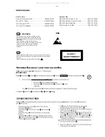
Output power ........................................... 2 x 2W RMS
Signal-to-noise ratio ..........................

t

 60 dBA (IEC)

Frequency response ....................... 125 – 16000 Hz
Impedance loudspeakers ........................................... 8

:

CD PLAYER

Frequency range ............................... 125 – 16000 Hz
Signal-to-noise ratio ............................................ 65 dBA

TUNER

FM wave range ................................... 87.5 – 108 MHz
MW wave range ................................ 531 – 1602 kHz
Sensitivity
– FM 26 dB sensitivity .......................................... 20 µV
– MW 26 dB sensitivity ................................... 5 mV/m
Total harmonic distortion .....................................

d

 5%

TAPE DECK

Frequency response

Normal tape (type I) ...... 125 – 8000 Hz (8 dB)

Signal-to-noise ratio

Normal tape (type I) ....................................  40 dBA

Wow and flutter ..............................................

d

 0.4% JIS

SPEAKERS

Bass reflex system
Dimensions (w x h x d) . 134 x 230 x 152 (mm)

GENERAL INFORMATION

AC Power ............................ 110 – 127 / 220 – 240 V

....................................................... 50/60 Hz, switchable

Dimensions (w x h x d) .. 148 x 233 x 216 (mm)
Weight (with/without speakers) ..................................

......................................................... approx. 3.65 / 1.53 kg

Power consumption

Active .......................................................................... 15 W
Standby .................................................................... < 4 W

Specifications and external appearance are
subject to change without notice.

SPECIFICATIONS

All manuals and user guides at all-guides.com

Summary of Contents for MCM159/61/98

Page 1: ...Printed in The Netherlands Subject to modification Micro System Version 1 1 CLASS 1 LASER PRODUCT 3141 785 32951 TABLE OF CONTENTS Page Location of PCBs Version Variations 1 2 Specifications 1 3 Measurement Setup 1 4 Service Aids Safety Instruction etc 1 5 CD Playability Check 1 6 to 1 7 Software Version Checking 2 Set Block Diagram 3 Set Wiring Diagram 4 Main Board 5 Front Board 6 Cass Board 7 Se...

Page 2: ...elector ECO Power Standby LCD Display Off USB Direct Type Versions Features in used 05 VERSION VARIATIONS Type Versions Board in used MCM159 Service policy MAIN BOARD CASS BOARD FRONT BOARD TIPS C Component Lever Repair M Module Lever Repair Used C 12 05 8 5 9 5 1 6 8 5 Feature diffrence C x C x MCM159 x All manuals and user guides at all guides com ...

Page 3: ...ion d 5 TAPE DECK Frequency response Normal tape type I 125 8000 Hz 8 dB Signal to noise ratio Normal tape type I 40 dBA Wow and flutter d 0 4 JIS SPEAKERS Bass reflex system Dimensions w x h x d 134 x 230 x 152 mm GENERAL INFORMATION AC Power 110 127 220 240V 50 60 Hz switchable Dimensions w x h x d 148 x 233 x 216 mm Weight with without speakers approx 3 65 1 53 kg Power consumption Active 15 W ...

Page 4: ... Voltmeter e g PM2534 DUT S N and distortion meter e g Sound Technology ST1700B Frame aerial e g 7122 707 89001 Tuner AM MW LW To avoid atmospheric interference all AM measurements have to be carried out in a Faraday s cage Use a bandpass filter or at least a high pass filter with 250Hz to eliminate hum 50Hz 100Hz RF Generator e g PM5326 Ri 50Ω Bandpass 250Hz 15kHz e g 7122 707 48001 LF Voltmeter ...

Page 5: ... ICs and many other semi conductors are susceptible to electrostatic discharges ESD Careless handling during repair can reduce life drastically When repairing make sure that you are connected with the same potential as the mass of the set via a wrist wrap with resistance Keep components and tools also at this potential ESD CLASS 1 LASER PRODUCT GB Safety regulations require that the set be restore...

Page 6: ...eck Laser current CD Drive offsets ok N Y check CD Drive offsets clean the lens check playability return set Customer complaint CD related problem return set return set replace CD Drive return set replace CD Drive return set replace Signal Processor return set fast lens cleaning 1 2 3 4 5 6 7 For flap loaders access to CD drive possible cleaning method 4 is recommended 1 7 For description see foll...

Page 7: ...directly The lens cleaning method 3 should be mentioned in the addendum sheet The final wording in national language as well as the printing is under responsibility of the Regional Service Organizations 3 FAST LENS CLEANING dry brush Use lens cleaning CD SBC AC300 9082 100 00043 Insert the lens cleaning CD press PLAY and follow the voice guide s instructions on the CD 4 LIQUID LENS CLEANING Becaus...

Page 8: ...TEST Display shows all patterns SKIP NEXT Display shows NEW SOFTWARE RESET VER refers to Version y yy refers to Software version number of the uProcessor counting up from 01 to 99 xx refers to date number of the production Display shows the MCU software version VER y yy MTP xx xx 2007 All manuals and user guides at all guides com ...

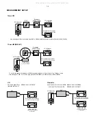
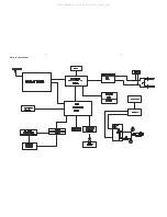
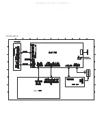
Page 9: ...3 1 3 1 SET BLOCK DIAGRAM All manuals and user guides at all guides com ...

Page 10: ...FRONT SET WIRING DIAGRAM 4 1 4 1 All manuals and user guides at all guides com ...

Page 11: ...ONTENTS Layout Top View 5 2 Layout Bottom View 5 3 Circuit Diagram AF Amp Part 5 4 Circuit Diagram CD MP3 Part 5 5 Circuit Diagram Tuner Part 5 6 5 1 5 1 All manuals and user guides at all guides com a l l g u i d e s c o m ...

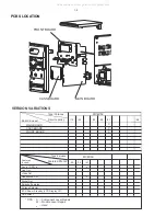
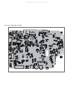
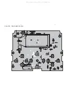
Page 12: ...5 2 5 2 PCB LAYOUT MAIN BOARD TOP VIEW All manuals and user guides at all guides com ...

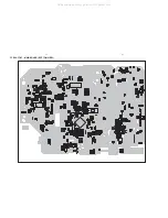
Page 13: ...5 3 5 3 PCB LAYOUT MAIN BOARD BOTTOM VIEW All manuals and user guides at all guides com ...

Page 14: ...5 4 5 4 CIRCUIT DIAGRAM MAIN POWER BOARD AF AMP PART All manuals and user guides at all guides com ...

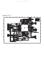
Page 15: ...5 5 5 5 CIRCUIT DIAGRAM MAIN BOARD CD MP3 PART All manuals and user guides at all guides com ...

Page 16: ...5 6 5 6 CIRCUIT DIAGRAM MAIN BOARD TUNER PART All manuals and user guides at all guides com a l l g u i d e s c o m ...

Page 17: ...FRONT BOARD TABLE OF CONTENTS Layout Top View 6 2 Layout Bottom View 6 3 Circuit Diagram 6 4 6 1 6 1 All manuals and user guides at all guides com ...

Page 18: ...6 2 PCB LAYOUT FRONT BOARD TOP VIEW 6 2 All manuals and user guides at all guides com ...

Page 19: ...6 3 PCB LAYOUT FRONT BOARD BOTTOM VIEW 6 3 All manuals and user guides at all guides com ...

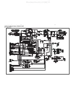
Page 20: ...6 4 CIRCUIT DIAGRAM FRONT BOARD 6 4 All manuals and user guides at all guides com ...

Page 21: ...CASSETTE BOARD TABLE OF CONTENTS Layout Top View 7 2 Layout Bottom View 7 2 Circuit Diagram 7 3 7 1 7 1 All manuals and user guides at all guides com a l l g u i d e s c o m ...

Page 22: ...7 2 PCB LAYOUT CASSETTE BOARD TOP VIEW 7 2 PCB LAYOUT CASSETTE BOARD BOTTOM VIEW All manuals and user guides at all guides com ...

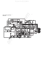
Page 23: ...7 3 7 3 CIRCUIT DIAGRAM CASSETTE BOARD All manuals and user guides at all guides com ...

Page 24: ...SET MECHANICAL EXPLODED VIEW 8 1 8 1 All manuals and user guides at all guides com ...

Page 25: ...96510016849 CASSETTE DOOR 61 205 996510018596 CASSETTE DOOR 98 206 996510016850 CD DOOR 61 206 996510018597 CD DOOR 98 208 996510016851 SOURCE BUTTON COVER 61 208 996510018601 SOURCE BUTTON COVER 98 209 996510016852 DBB BUTTON COVER 61 209 996510018603 DBB BUTTON COVER 98 210 996510016853 PLAY BUTTON COVER 61 210 996510018602 PLAY BUTTON COVER 98 211 996510016854 STOP BUTTON COVER 61 211 996510018...

Page 26: ...normal service parts IC2 996500039806 IC ET2314 SOP28 IC802 994000004622 IC LA6548NH JACK1 994000004369 PHONE JACK TC38 063 05 01 JACK2 996510000889 PHONE JACK TC38 060 01 RING L28 996510000887 FM COIL 3x19 5T L29 996510000888 FM COIL 5x3 5T L31 996500039350 FM COIL 4 5X2 5T 0 8MM L32 996510000888 FM COIL 5x3 5T Q10 996500038609 TRANSISTORS 2W 8050C Q11 994000001193 TRANSISTORS KSB772YS Q12 994000...

Page 27: ...2444 TACT SWITCH 6x6mm 4 3mm SW4 996500042444 TACT SWITCH 6x6mm 4 3mm SW5 996500042444 TACT SWITCH 6x6mm 4 3mm SW6 996500042444 TACT SWITCH 6x6mm 4 3mm SW7 996500042444 TACT SWITCH 6x6mm 4 3mm SW8 996500042444 TACT SWITCH 6x6mm 4 3mm SW9 996500042444 TACT SWITCH 6x6mm 4 3mm U10 996510006682 MCU GY390 FLASH U8 994000001236 IC M24C01 WMN6 U9 994000002839 IC H1117SJ 3 3V X3 994000004615 CRYSTAL 32 76...

Page 28: ...T 1 0 Manual 3141 785 32950 Initial Service Manual released 1 1 Manual 3141 785 32951 In this version version 98 added Page 8 2 Mechanical Accessories Parts List is updated All manuals and user guides at all guides com ...

Reviews: