background image

6-1

6-1

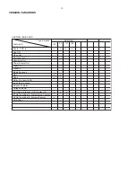
MAIN  BOARD

TABLE OF CONTENTS

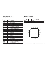
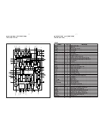
Internal IC Diagram ............................................... 6-1 to 6-5

Main Board(5757) Layout Top View ................................ 6-6

Main Board(5757) Layout Bottom View .......................... 6-7

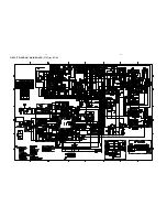
Circuit Diagram - Main Board(5757) ............................... 6-8

HP Jack Board .................................................................  6-9

Electrical Parts List ........................................................ 6-10

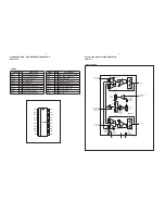
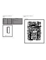
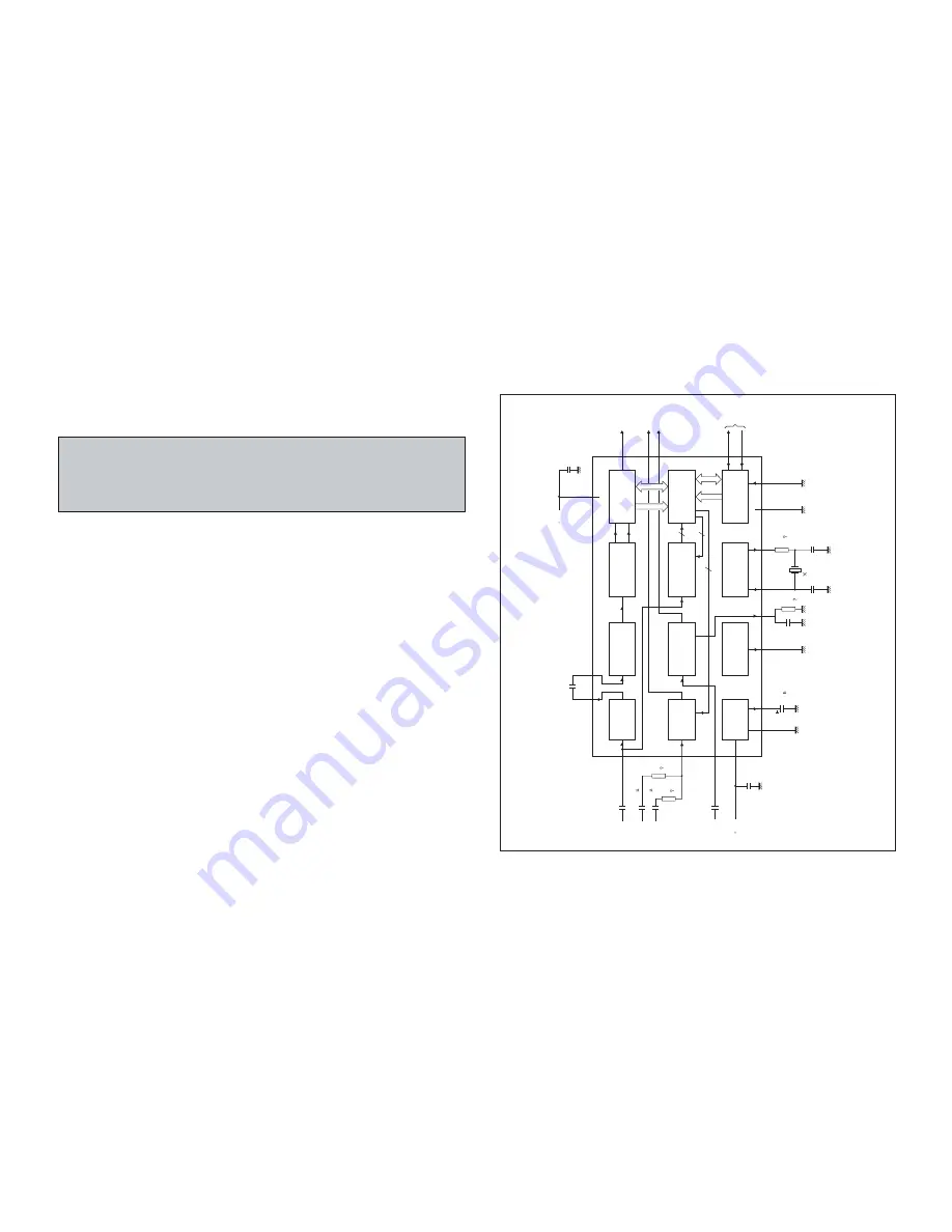
BLOCK DIAGRAM - RDS/RBDS PRE-PROCESSOR
SAA6588T

BLOCK DIAGRAM

MGK535

10

k

10

k

470

k

57 kHz

8th ORDER

BAND-P

ASS

PA

U

S

E

DETECT

OR

MUL

TI-P

A

TH

DETECT

OR

CLOCKED

COMP

ARA

T

OR

SIGNAL

 QUALITY

DETECT

OR

RDS/RDBS

DEMODULA

T

OR

INTERF

ACE

REGISTER

POWER

SUPPL

Y

AND RESET

TEST

CONTROL

C10

C9

100 nF

DA

VN

data

available

pause

output

multi-path

output

8

7

19

18

11

2

9

10

V

NI

C

T

U

O

C

S

DDD

560 pF

OSCILLA

T

OR

AND CLOCK

I

2

C-BUS SLA

VE

TRANSCEIVER

I

2

C-BUS

RDS/RDBS

DECODER

multiplex

input

audio

inputs

level

input

4

4

SAA6588

TCON

MRO

100

nF

C6

100 nF

C8

C1

1

C2

C3

20

14

13

16

R3

R2

2.2 nF

330 pF

LV

IN

V

DDA

AFIN

MPX

C7

2.2

F

0.47

F

0.47

F

C1

3

1

OSCI

5

Q1

n

4.332

MHz

n = 1 to 4

OSCO

4

R1

C5

82 pF

C4

47 pF

1 k

MAD

12

V

SSD

6

R4

V

ref

V

SSA

17

15

5

5 V

5 V

PSWN

MPTH

SDA

SCL

Summary of Contents for MCM276R/37

Page 1: ...o Printed in The Netherlands Subject to modification GB 3141 785 31241 Micro System TABLE OF CONTENTS Page Location of PC Boards Versions Variation 1 2 Specifications 1 3 Measurement Setup 1 4 Service Aids Safety Instruction etc 1 5 to 1 7 Lead free Information Service Instruction 1 8 Preparations Controls 1 9 to 1 10 Troubleshooting 1 11 Disassembly Instructions Service positions 2 Service Test P...

Page 2: ...ix Surround RDS x x News x x Dolby Pro Logic DPL Incredible Surround Karaoke Features Voltage Selector ECO Power Standby LCD Display Off x x ECO6 Tuner Board Systems Non Cenelec x ECO6 Tuner Board Systems Cenelec x x USB Direct VERSION VARIATIONS Type Versions MCM276R Features Board in used x x 05 x x x x x VERSION VARIATIONS ...

Page 3: ... 18dB IF rejection 45dB Image rejection 28dB Distortion at RF 50mV M 80 5 AMPLIFIER Output power L R 2 x 5 0W 4Ω 1kHz 10 THD Frequency response within 3dB 50Hz 16kHz Digital Sound Control DSC Jazz Rock Pop Classic Input sensitivity Aux in at 1kHz 500mV at 600 Ω Output sensitivity Headphone output at 32 Ω 10mW 2dB Max vol COMPACT DISC Frequency response within 3dB 125Hz 16kHz Output level in Vrms 5...

Page 4: ...15kHz e g 7122 707 48001 LF Voltmeter e g PM2534 DUT S N and distortion meter e g Sound Technology ST1700B Frame aerial e g 7122 707 89001 Tuner AM MW LW To avoid atmospheric interference all AM measurements have to be carried out in a Faraday s cage Use a bandpass filter or at least a high pass filter with 250Hz to eliminate hum 50Hz 100Hz RF Generator e g PM5326 Ri 50Ω Bandpass 250Hz 15kHz e g 7...

Page 5: ...t Disc 4822 395 10216 ESD Equipment Anti static table mat large 1200x650x1 25mm 4822 466 10953 anti static table mat small 600x650x1 25mm 4822 466 10958 Anti static wristband 4822 395 10223 Connectorbox 1MΩ 4822 395 11307 Extension cable to connect wristband to conn box 4822 320 11305 Connecting cable to connect table mat to conn box 4822 320 11306 Earth cable to Connect product to mat or box 4822...

Page 6: ...n osservazione della più grande cauzione alla loro manipolazione Durante le riparazioni occorre quindi essere collegato allo stesso potenziale che quello della massa dell apparecchio tramite un braccialetto a resistenza Assicurarsi che i componenti e anche gli utensili con quali si lavora siano anche a questo potenziale Pour votre sécurité ces documents doivent être utilisés par des spécia listes ...

Page 7: ...es has to be purchased at external companies Special information for BGA ICs always use the 12nc recognizable soldering temperature profile of the specific BGA for de soldering always use the lead free temperature profile in case of doubt lead free BGA ICs will be delivered in so called dry packaging sealed pack including a silica gel pack to protect the IC against moisture After opening dependent...

Page 8: ...e Rear Portion and PCBs Figure 3 Figure 2 Dismantling the Rear Portion and PCBs 5 Loosen 2 screws E to remove the Bracket Jack Board as shown in Figure 4 6 Loosen 3 screws F to remove the Main Board as shown in figure 5 Figure 4 Figure 5 Figure 1 Dismantling of the Display Lens the Volume knob 1 Use a flat head screw driver to give a push in the direction as shown in figure 6 Figure 6 2 Place two ...

Page 9: ... Loosen 5 screws J mounting the Key Board to the Front Cabinet to remove the Key Board as shown in figure 8 2 Loosen 4 screws H and 3 screws G to CD Module as shown in figure 8 3 Loosen 2 screws I to remove the Servo Motor Mechanism as shown in figure 8 Figure 8 4 Loosen 4 screws K to remove the Right CD Door Carrier and 4 screws L to remove the Left CD Door Carrier as shown in figure 9 Figure 9 S...

Page 10: ...d 5V Display shows ADC3 Value for ADC3 Input Line Door switch status Y Y N N Display shows Table 1 KEY TEST Button pressed 9 Button pressed Display shows the MCU version MCU Vyy Main menu V refers to Version yy refers to Software version number of the uProcessor counting up from 01 to 99 To enter Service Testprogram hold PLAY Door Open Close buttons depressed while plugging mainscord in Door switc...

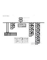
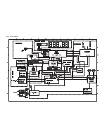
Page 11: ...4 1 4 1 SET BLOCK DIAGRAM ...

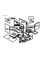
Page 12: ...SET WIRING DIAGRAM 5 1 5 1 ...

Page 13: ...SIGNAL QUALITY DETECTOR RDS RDBS DEMODULATOR INTERFACE REGISTER POWER SUPPLY AND RESET TEST CONTROL C10 C9 100 nF DAVN data available pause output multi path output 8 7 19 18 11 2 9 10 V N I C T U O C S DDD 560 pF OSCILLATOR AND CLOCK I 2 C BUS SLAVE TRANSCEIVER I 2 C BUS RDS RDBS DECODER multiplex input audio inputs level input 4 4 SAA6588 TCON MRO 100 nF C6 100 nF C8 C11 C2 C3 20 14 13 16 R3 R2 ...

Page 14: ...ef 17 refHUHQFH vROWDJH RXWSXW SCOUT 18 EDQG SDVV OWHU RXWSXW CIN 19 FRPSDrDWRU LQSXW LVIN 20 levHO LQSXW SYMBOL PIN DESCRIPTION MRO MPTH TCON OSCO OSCI VSSD VDDD SDA SCL LVIN CIN SCOUT Vref VSSA VDDA MPX AFIN MAD 1 2 3 4 5 6 7 8 9 10 11 12 20 19 18 17 16 15 14 13 MGK534 DAVN PSWN SAA6588T PIN DESCRIPTION RDS RBDS PRE PROCESSOR SAA6588T BLOCK DIAGRAM mute stand by switch input MLC351 output 1 15 k...

Page 15: ...NDOW DETECTOR LAST STATION MEMORY AM FM INDICATOR IN LOCK DETECTOR FM DETECTOR PILOT DETECTOR CHARGE PUMP MULTIPLEXER CRYSTAL OSCILLATOR SHIFT REGISTER FM FRONT END FM OSCILLATOR FM IF2 FM IF1 FM MIXER SEQUENTIAL CIRCUIT STATUS REGISTER AM FRONT END AM OSCILLATOR AM DETECTOR V I CONVERTER AM MIXER AM IF AGC AFC hard mute level PLL DECODER MATRIX SDS MUTE up down level RFGND DATA BUS CLOCK WRITE EN...

Page 16: ...l a t s y r c 5 2 L A T X d n u o r g l a t i g i d 6 2 D N G D BUS CLOCK 27 bus clock input t u p t u o t u p n i a t a d s u b 8 2 A T A D WRITE ENABLE 29 bus write enable input 0 P t r o p t u p t u o e l b a m m a r g o r p 0 3 0 P 1 P t r o p t u p t u o e l b a m m a r g o r p 1 3 1 P t i u c r i c C L z H k 0 5 4 2 3 C F A 0 3 3 l a c i p y t e c n a d e p m i t u p n i 2 t u p n i F I M F ...

Page 17: ... e d o e r e t s 1 1 I X P M t u p n i r e t l p o o l 2 1 I F L t u p n i e t u m 3 1 E T U M k 3 4 l a c i p y t e c n a d e p m i t u p t u o t u p t u o l e n n a h c t f e l 4 1 O L F A k 3 4 l a c i p y t e c n a d e p m i t u p t u o t u p t u o l e n n a h c t h g i r 5 1 O R F A t u p n i r e t l r o t c e t e d t o l i p 6 1 L I F L I P e g a t s X P M d n a r o t c e t e d F I f o d n u...

Page 18: ...6 6 6 6 LAYOUT DIAGRAM MAIN BOARD 5757 for 37 98 TOP SIDE ...

Page 19: ...6 7 6 7 LAYOUT DIAGRAM MAIN BOARD 5757 for 37 98 BOTTOM SIDE ...

Page 20: ...6 8 6 8 CIRCUIT DIAGRAM MAIN BOARD 5757 for 37 98 ...

Page 21: ...6 9 6 9 LAYOUT DIAGRAM HP JACK BOARD TOP SIDE LAYOUT DIAGRAM HP JACK BOARD BOTTOM SIDE CIRCUIT DIAGRAM HP JACK BOARD ...

Page 22: ...1 CD MCU BOARD TABLE OF CONTENTS Main Board Layout Top View 7 2 Main Board Layout Bottom View 7 3 Circuit Diagram CD Part 7 4 Circuit Diagram MCU Part 7 5 Layout Diagram SW Board 7 6 Electrical Parts List 7 6 ...

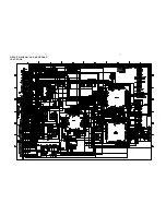
Page 23: ...7 2 7 2 LAYOUT DIAGRAM CD MCU BOARD TOP SIDE ...

Page 24: ...7 3 7 3 LAYOUT DIAGRAM CD MCU BOARD BOTTOM SIDE ...

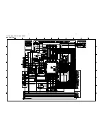
Page 25: ...7 4 7 4 CIRCUIT DIAGRAM CD MCU BOARD CD PORTION ...

Page 26: ...CIRCUIT DIAGRAM CD MCU BOARD MCU PORTION 7 5 7 5 ...

Page 27: ...7 6 7 6 LAYOUT DIAGRAM LIMIT SWITCH BOARD TOP SIDE LAYOUT DIAGRAM LIMIT SWITCH BOARD BOTTOM SIDE ...

Page 28: ...t controller and the HT1622 are all enabled 2 RD I READ clock input with Pull high resistor Data in the RAM of the HT1622 are clocked out on the rising edge of the RD signal The clocked out data will appear on the data line The host con troller can use the next falling edge to latch the clocked out data 3 WR I WRITE clock input with Pull high resistor Data on the DATA line are latched into the HT1...

Page 29: ...LAYOUT DIAGRAM AC POWER BOARD TOP SIDE 8 2 8 2 LAYOUT DIAGRAM AC POWER BOARD BOTTOM SIDE ...

Page 30: ...8 3 8 3 CIRCUIT DIAGRAM AC POWER BOARD ...

Page 31: ...OARD TOP SIDE LAYOUT DIAGRAM AC SOCKET BOARD BOTTOM SIDE LAYOUT DIAGRAM DOOR MOTOR BOARD TOP SIDE LAYOUT DIAGRAM DOOR MOTOR BOARD BOTTOM SIDE LAYOUT DIAGRAM RC BOARD TOP SIDE LAYOUT DIAGRAM RC BOARD BOTTOM SIDE CIRCUIT DIAGRAM RC BOARD ...

Page 32: ...LAYOUT DIAGRAM DISPLAY BOARD TOP SIDE 8 5 8 5 LAYOUT DIAGRAM DISPLAY BOARD BOTTOM SIDE CIRCUIT DIAGRAM DISPLAY BOARD ...

Page 33: ...8 6 8 6 LAYOUT DIAGRAM KEY BOARD TOP SIDE LAYOUT DIAGRAM KEY BOARD BOTTOM SIDE CIRCUIT DIAGRAM KEY BOARD ...

Page 34: ...CIRCUIT DIAGRAM SP ANT BOARD 8 7 8 7 LAYOUT DIAGRAM SP ANT BOARD TOP SIDE LAYOUT DIAGRAM SP ANT BOARD BOTTOM SIDE ...

Page 35: ...9 1 9 1 SET MECHANICAL EXPLODED VIEW 1 ª º 2 4 7 8 9 3 5 6 ...

Page 36: ...04315 COVER PLAY BUTTON 32 9940 000 04309 BUTTON FW FF 33 9965 000 41789 PANEL FUNCTION 34 9965 000 41797 COVER FUNCTION PANEL 35 9940 000 04311 BUTTON FUNCTION 36 9940 000 04308 BUTTON PLAY 37 9940 000 04333 IR LENS 38 9940 000 04316 PULLEY SERVO MOTOR 39 9940 000 04314 BRACKET FUNCTION PANEL 9940 000 04331 AM LOOP ANT 164X75MM 9940 000 04421 FM ANT WIRE 2P 300R L 2 6M 9940 000 04798 PLASTIC WALL...

Page 37: ...3141 785 31240 Initial Service Manual released 1 1 Manual 3141 785 31241 In this version Mechanical Accessories Partslist Page 9 2 has been updated the Remote Control changed as below 9965 100 06738 Remote Control was 9940 000 41787 ...

Reviews: